

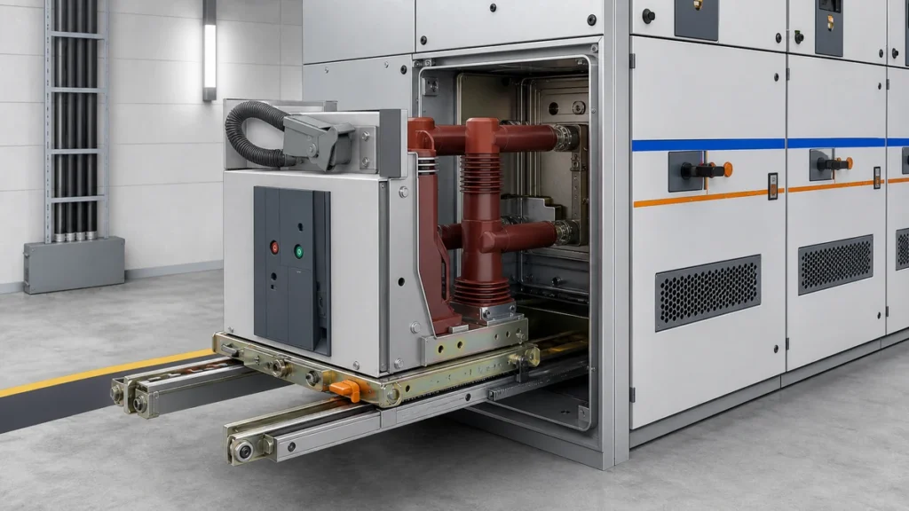
Quick Takeaway
- Confirm the project duty and applicable requirements for Switchgear Handcarts before selection or service work.
- Use recorded inspection and test evidence instead of unsupported assumptions.
- Keep the final acceptance, maintenance, and handover documents with the equipment record.
Before committing to a replacement or spare chassis truck, use the Chassis Trucks Racking Systems selection context to identify the component family, then verify fit against the actual switchgear assembly drawings and the original manufacturer's documentation — not a product photograph or a nameplate alone. Dimensional and interlock mismatches between a chassis truck and its cell can prevent correct racking, defeat safety interlocks, and leave the assembly non-compliant with IEC 62271-200:2021.
Why Compatibility Is Not Assumed
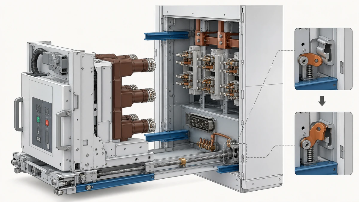
A chassis truck carries the vacuum circuit breaker (VCB) into and out of its service position, aligns primary disconnecting contacts, and engages the cell's interlock system at defined travel positions. Each of those functions depends on physical geometry, contact geometry, and interlock engagement points that are specific to a switchgear assembly design. IEC 62271-200:2021 covers AC metal-enclosed switchgear assemblies from above 1 kV up to 52 kV and addresses earthing circuit requirements and interlocks as part of the assembly as a whole. That framing matters: the standard treats the cell and the removable part as an integrated system, so a truck that passes dimensional inspection in isolation may still fail as part of the assembly if its interlock geometry differs from the original.
IEC 62271-1:2017 establishes common specifications across the switchgear family but is explicit that compatibility must be evaluated against the relevant assembly documentation and the manufacturer's own records rather than a broad product description. Neither standard authorizes interchangeability between trucks from different manufacturers or different assembly series without that specific verification.
The practical consequence: a truck described as "suitable for" a particular VCB model is describing breaker-to-truck fit, not cell-to-truck fit. Both dimensions of compatibility must be confirmed independently.
Interface Categories That Require Direct Verification
Chassis truck compatibility breaks into four interface categories. Each carries its own failure mode if mismatched.
**Primary disconnecting contacts.** The tulip or cluster contacts on the truck side must align axially and radially with the fixed contacts in the cell at the fully racked-in position. Contact force, wipe distance, and insertion depth are set by the truck's travel geometry. An incorrect truck will either under-insert (raising contact resistance and heating) or over-travel (damaging contacts or the cell structure). Verify contact type, finger count, pitch, and rated current against the cell's original equipment manufacturer (OEM) specification.
**Secondary (control and auxiliary) disconnecting contacts.** These are typically a multi-pin block or plug that engages at a defined racking position. Compare the specified assembly interface with the relevant Secondary Connectors Control components data, but confirm pin count, connector body type, engagement depth, and keying orientation against the cell documentation. A secondary connector that partially engages may allow the truck to reach the service position while leaving protection, signaling, or trip circuits open — a dangerous state that may not be immediately apparent.
**Earthing circuit continuity.** IEC 62271-200:2021 includes requirements related to the earthing circuit of the removable part. The chassis truck typically carries the breaker frame earth back to the cell earth bar through a sliding contact or a plug-in connection. If this interface is geometrically incompatible, the removable part may be unearthed in the test or disconnected position even though it appears correctly seated.
**Racking mechanism engagement.** The racking screw, rack-and-pinion, or lever drive engages a specific point on the truck chassis. Pitch, engagement depth, and stop-position geometry determine where the truck halts at each defined position (disconnected, test, service). A mismatch shifts these stop points, which shifts the interlock engagement window.
Interlock System Review
Modern IEC 62271-200 switchgear uses position-dependent interlocks to prevent incorrect operations. The interlock chain typically covers: breaker cannot be racked while closed, earthing switch cannot be closed with the breaker in the service position, compartment door cannot be opened while the breaker is in the service position, and the breaker cannot close unless fully in the service or test position.
Each of these interlocks depends on a mechanical cam, pin, or lever on the truck reaching a fixed receiver in the cell at the correct travel position. If the truck's interlock geometry does not match the cell's receivers — because the truck is from a different series, a different generation, or a nominally similar but dimensionally variant product — the interlock may:
- Engage early, preventing full racking-in.
- Engage late, allowing the breaker to close before the contacts are fully made.
- Fail to engage at all, leaving the interlock chain incomplete.
None of these conditions is safe. The third is the most dangerous because it may not produce a visible or audible failure signal during racking. Verify each interlock engagement point against the cell drawing before installation.
Racking Travel Dimensions: What to Measure
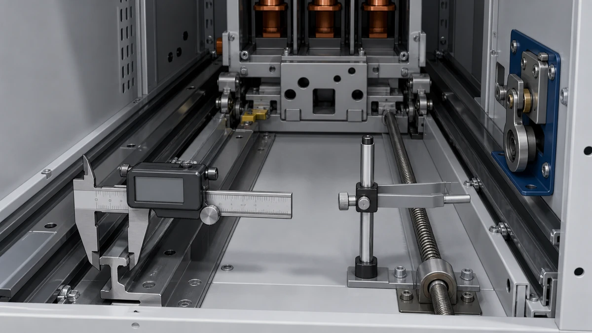
Racking travel is the total linear or rotational displacement of the truck between the fully disconnected and fully service positions. It is set by the cell design and is not adjustable on the truck. The following dimensions must match the cell specification:
- Total racking travel (mm or degrees of rack rotation)
- Distance from the disconnected-position stop to the test-position interlock engagement point
- Distance from the test-position stop to the service-position contact make point
- Chassis width and depth against cell guide rail spacing
- Wheel or runner diameter and flange profile against the cell rail profile
- Height from the floor of the cell to the primary contact centerline
Guide rail profile is a common source of incompatibility that is not captured by a VCB nameplate check. Cells from the same manufacturer but different production eras may use different rail profiles. Measure the rail cross-section in the cell, not just the nominal width.
VCB-to-Truck Interface
This is a separate verification from cell-to-truck fit. The VCB mounts to the truck chassis via a defined cradle or frame, and the mounting points, isolation distances, and breaker terminal positions must all be compatible. The applicable Vacuum Circuit Breakers category helps identify the breaker family, but a truck cradle designed for a drawout VCB of one frame size will not correctly support a different frame size even if the overall chassis dimensions appear similar.
Confirm: mounting hole pattern and bolt size, cradle depth (breaker sinks to the correct height for contact alignment), isolation clearances between live parts and the truck frame, and the mechanical trip/close interlock interface if the cell uses a mechanical interlock to the breaker mechanism.
Data to Collect Before an RFQ or Replacement Decision
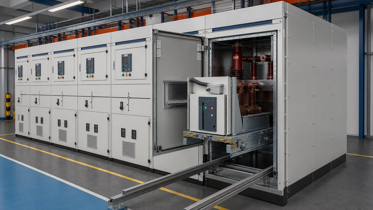
Procurement decisions made from a type designation alone regularly produce incompatible trucks. The following data must be in hand before issuing an RFQ:
- Switchgear assembly manufacturer, assembly series designation, and switchgear cell number from the single-line or panel schedule
- Year of manufacture and any documented modification history for the cell
- OEM drawing numbers for the chassis truck, the cell interior, and the racking mechanism
- Rated voltage, rated normal current, and rated short-circuit current of the cell (determines contact force requirements)
- Position of the test-position auxiliary contact engagement relative to the racking travel datum
- Interlock cam profile drawing or interlock engagement dimension table
- Guide rail cross-section profile drawing
- Secondary connector part number and pin assignment
If any of these are missing, the correct path is to request them from the original switchgear manufacturer before specifying a replacement. Where a documented compatibility review is needed after the records are collected, use Contact Us with the drawings and cell data rather than approving a substitute from a photograph. Substitution from a supplier's cross-reference alone does not satisfy the IEC 62271-1:2017 requirement that compatibility be evaluated against the relevant assembly and manufacturer documentation.
Failure Risks from Incompatible Trucks
Understanding the failure modes informs the inspection checklist. An incompatible chassis truck can produce:
- Contact overheating from insufficient insertion depth or contact force, leading to thermal damage at the primary disconnecting contacts.
- Breaker trip failure if the secondary connector does not fully engage and leaves the trip coil circuit open.
- Interlock bypass if the interlock cam geometry misses the receiver, leaving the assembly in an unsafe state that passes visual inspection.
- Mechanical damage to the cell guide rails, racking mechanism, or breaker if the truck is forced past a binding point.
- Earthing continuity loss on the removable part, creating a shock hazard during access to the disconnected breaker.
Each of these is a commissioning or maintenance risk, not just a procurement inconvenience. Model-specific approved procedures govern the actual installation and racking verification steps; those procedures are the governing authority for torque values, contact resistance test limits, and functional interlock test sequences.
Pre-Installation Acceptance Checklist
| Check item | Acceptance criterion | Status | Evidence reference |
|---|---|---|---|
| Assembly series and cell number confirmed against OEM documentation | Truck OEM part number traced to this specific assembly series | ☐ | Cell nameplate + OEM drawing register |
| Primary contact type, finger count, and rated current match | Exact match to cell primary contact drawing | ☐ | OEM contact drawing |
| Secondary connector type, pin count, and keying match | Exact match; keying prevents incorrect orientation | ☐ | Secondary connector part number + pin assignment sheet |
| Racking travel dimension matches cell specification | Total travel within ±1 mm of cell drawing datum (or per OEM tolerance) | ☐ | Cell racking mechanism drawing |
| Guide rail cross-section profile matches cell rails | Profile gauge or caliper measurement matches rail drawing | ☐ | Cell interior drawing; physical measurement |
| Interlock cam engagement verified at each defined position | Cam reaches receiver and operates interlock at disconnected, test, and service positions | ☐ | Interlock engagement dimension table; functional test record |
| Earthing continuity interface present and geometrically compatible | Sliding contact or plug-in earth connection present; continuity test result on file | ☐ | IEC 62271-200:2021 earthing requirement; test record |
| VCB cradle mounting pattern and isolation clearances match breaker frame | Bolt pattern matched; clearances not reduced below rated isolation distance | ☐ | Truck cradle drawing + VCB frame drawing |
| No modification history on cell that changes interface geometry | Cell modification records reviewed; no dimensional changes to truck interfaces | ☐ | Cell modification register |
| Approved installation procedure available before work begins | Model-specific OEM or switchgear integrator procedure on site | ☐ | Procedure document number |
FAQ
What is the primary standard governing VCB chassis truck compatibility in metal-enclosed switchgear?
IEC 62271-200:2021 is the primary standard for AC metal-enclosed switchgear assemblies from above 1 kV up to 52 kV and covers earthing circuit requirements and interlocks for the assembly as a whole, treating the cell and the removable part as an integrated system. IEC 62271-1:2017 provides common switchgear specifications and explicitly states that compatibility must be evaluated against the relevant assembly documentation and manufacturer records. Neither standard defines a universal fit criterion that allows cross-manufacturer substitution without that specific verification.
What is the difference between VCB-to-truck compatibility and truck-to-cell compatibility?
VCB-to-truck compatibility concerns whether the vacuum circuit breaker's frame, mounting pattern, terminal positions, and isolation clearances match the truck cradle. Truck-to-cell compatibility concerns whether the truck's racking travel, interlock cam geometry, guide rail profile, primary contact alignment, secondary connector, and earthing interface match the switchgear cell. A truck can be fully compatible with a particular VCB and still be incompatible with the cell it will be installed in. Both must be confirmed against OEM documentation independently.
What are the interlock positions that must be verified during a chassis truck replacement?
The interlock system must be verified at the disconnected position, the test position, and the service position. At each position, the truck's interlock cam or pin must reach and positively engage the corresponding receiver in the cell. The interlock chain typically prevents the breaker from being racked while closed, prevents the earthing switch from closing with the breaker in service, and prevents door access while the breaker is in the service position. Each engagement point has a defined geometric window; a mismatched truck may pass visual inspection while leaving one or more links of the chain incomplete.
What documents are required before issuing an RFQ for a replacement chassis truck?
The minimum required documents are: the switchgear assembly manufacturer name, assembly series, and cell number; OEM drawing numbers for the chassis truck, cell interior, and racking mechanism; the secondary connector part number and pin assignment; the interlock engagement dimension table or cam profile drawing; the guide rail cross-section drawing; and the cell modification register confirming that no dimensional changes have been made to truck interfaces since original manufacture. A supplier's cross-reference or a photograph of the existing truck is not sufficient. Missing documents should be requested from the original switchgear manufacturer before the RFQ is issued.
Can a chassis truck from a different manufacturer be substituted if the VCB nameplate matches?
No. The VCB nameplate confirms electrical ratings and the breaker model, not the dimensional and interlock geometry of the truck or its fit to a specific cell. IEC 62271-1:2017 requires compatibility to be evaluated against the relevant assembly documentation and the manufacturer's own records rather than a broad product description. Cross-manufacturer substitution requires a full dimensional comparison against cell OEM drawings for every interface identified in this checklist, and in many cases the original switchgear manufacturer's written approval as well.
What failure modes indicate a chassis truck was installed with incorrect racking travel geometry?
The most common indicators are: excessive resistance during racking (the truck binds before reaching the service-position stop), the primary contact resistance measurement after racking-in is above the acceptable limit, the secondary connector does not seat fully and auxiliary circuits show open-circuit conditions, or one or more interlocks do not operate at the expected racking position. Mechanical damage to guide rails, the racking screw, or the truck frame also suggests a geometry mismatch. These conditions require halting the installation and returning to OEM documentation before proceeding; model-specific approved procedures govern the diagnostic and corrective steps.

