

Quick Takeaway
- Confirm the project duty and applicable requirements for Vacuum Circuit Breakers before selection or service work.
- Use recorded inspection and test evidence instead of unsupported assumptions.
- Keep the final acceptance, maintenance, and handover documents with the equipment record.
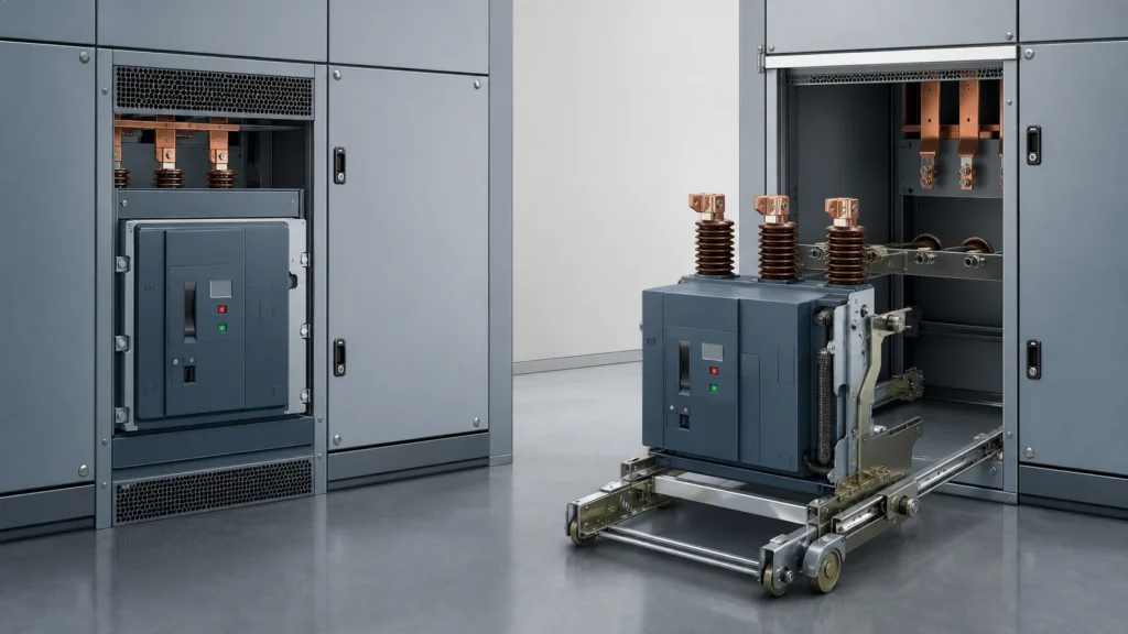
The core difference between a fixed and a drawout vacuum circuit breaker is not the interrupting technology — both use a vacuum interrupter — but the mechanical and electrical interface that connects the breaker to its switchgear enclosure. A fixed breaker is bolted permanently into its compartment with hardwired connections, while a drawout (withdrawable) breaker sits on a racking mechanism that lets it slide between connected, test, and disconnected positions without disturbing the primary bus. When a replacement review begins, the mounting type dictates which interface evidence you must verify before issuing an RFQ, because swapping one arrangement for the other is never a drop-in exercise.
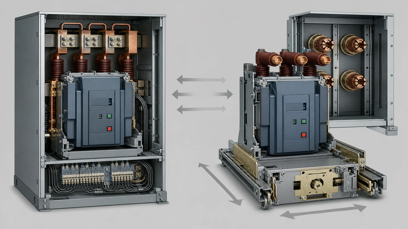
| Characteristic | Fixed arrangement | Drawout (withdrawable) arrangement |
|---|---|---|
| Primary connection method | Bolted bus bar joints, hardwired | Plug-in or tulip contacts on racking rails |
| Isolation for maintenance | Upstream isolation required; breaker stays in place | Breaker racks out to test or disconnected position |
| Mechanical interface | Mounting frame, fixed bolting pattern | Cradle, racking mechanism, guide rails, interlock cam |
| Auxiliary-circuit interface | Terminal block, hardwired | Self-aligning auxiliary plug connector |
| Earthing interface | Permanent earth bus bolted in compartment | Earth contacts engage automatically in disconnected position |
| Typical application emphasis | Compact substations, lower-frequency maintenance sites | Industrial plants, utility distribution, frequent maintenance or testing |
Why the Mounting Arrangement Drives the Replacement Review
A vacuum circuit breaker replacement that stays within the same mounting arrangement — fixed-for-fixed or drawout-for-drawout — still requires dimensional and interface verification, but the scope of that verification is contained. The moment the replacement crosses mounting types, additional evidence categories come into play: structural modification of the switchgear housing, rerouting of primary and auxiliary conductors, earthing path continuity, and mechanical interlock compatibility. Schneider Electric's EvoPacT HVX-O integration guide identifies five documented switchgear integration considerations — mechanical fixation, earthing, medium-voltage electrical connections, auxiliary-circuit interfaces, and racking interfaces — each of which changes character depending on whether the breaker is fixed or withdrawable. Understanding this list before the review begins prevents scope creep after an order is placed.
Functional Distinction: What Each Arrangement Actually Does Differently
Both arrangements accomplish the same electrical function: making, carrying, and breaking load and fault current through a vacuum interrupter. The divergence is entirely in the serviceability and isolation method.
A fixed breaker relies on external upstream devices — a switch-disconnector, an isolator, or a de-energised bus section — to create a safe maintenance zone. The breaker itself cannot be separated from live conductors without unbolting hardware. This is adequate where maintenance intervals are long, where the switchgear serves a single radial feeder, or where the installation footprint must be minimised.
A drawout breaker carries its own isolation capability. Racking the breaker from the connected position to the test position opens the primary contacts from the bus while keeping the auxiliary circuits available for secondary injection testing. Racking further to the fully disconnected or removed position opens both primary and auxiliary interfaces. This self-contained isolation cycle is why drawout breakers dominate in industrial motor-control centres and utility ring-main units where planned outages must be short.
Interface and Configuration Dependencies That Change Between Arrangements
Mechanical Fixation
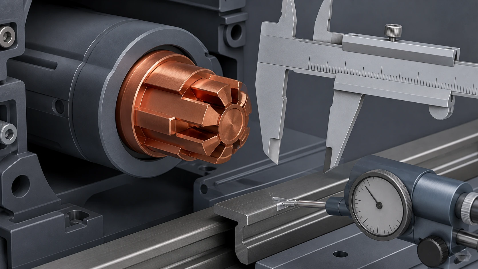
A fixed breaker's mounting frame is designed around a specific bolt pattern and enclosure depth. The replacement breaker must match these dimensions or require adapter plates. A drawout breaker instead depends on a cradle and guide-rail geometry. Replacing one drawout breaker with another brand or generation demands confirmation that the rail pitch, cradle depth, and racking-lever engagement are compatible, because even small deviations can prevent the breaker from reaching the connected position or from engaging its safety interlocks.
Medium-Voltage Electrical Interface
Fixed arrangements use bolted bus connections — typically flat copper or aluminium bars torqued to the breaker's primary terminals. The conductor geometry, spacing, and phase clearances are set at installation and do not change unless the compartment is re-engineered. Drawout arrangements use plug-in primary contacts (often tulip-type contacts or similar self-aligning designs) mounted on the switchgear's stationary portion. The replacement breaker's moving primary contacts must mate dimensionally and must deliver the required contact pressure against these stationary contacts to maintain the rated current path.
Auxiliary-Circuit Interface
In a fixed breaker, the auxiliary wiring — trip coils, close coils, position indicators, motor-charge circuits — terminates on a fixed terminal block with individual conductors. A drawout breaker consolidates these circuits into a multi-pin auxiliary plug that engages automatically as the breaker reaches the connected position. A replacement review must confirm pin assignment, voltage rating, and connector geometry of this plug, because a mismatch can leave protection or control circuits open without any visible indication.
Earthing Interface
Schneider Electric's integration documentation lists the earthing interface as a distinct verification category. Fixed breakers typically share a compartment earth bus bolted directly to the switchgear frame. Drawout breakers include an automatic earthing contact — a sliding or spring-loaded conductor that connects the breaker frame to the switchgear earth bus when the breaker is in any racked position. A replacement breaker must maintain this automatic earthing path, and the contact alignment and engagement force must be verified against the switchgear manufacturer's specification.
Racking Interface (Drawout Only)
The racking mechanism itself — the screw drive, lever, or motor that moves the breaker between positions — is sometimes integral to the switchgear and sometimes supplied with the breaker. The replacement review must establish which component owns the racking function and whether the new breaker's travel, interlock positions, and shutter engagement match the existing cradle. This category has no equivalent in a fixed arrangement.
Standards and Evidence Boundaries
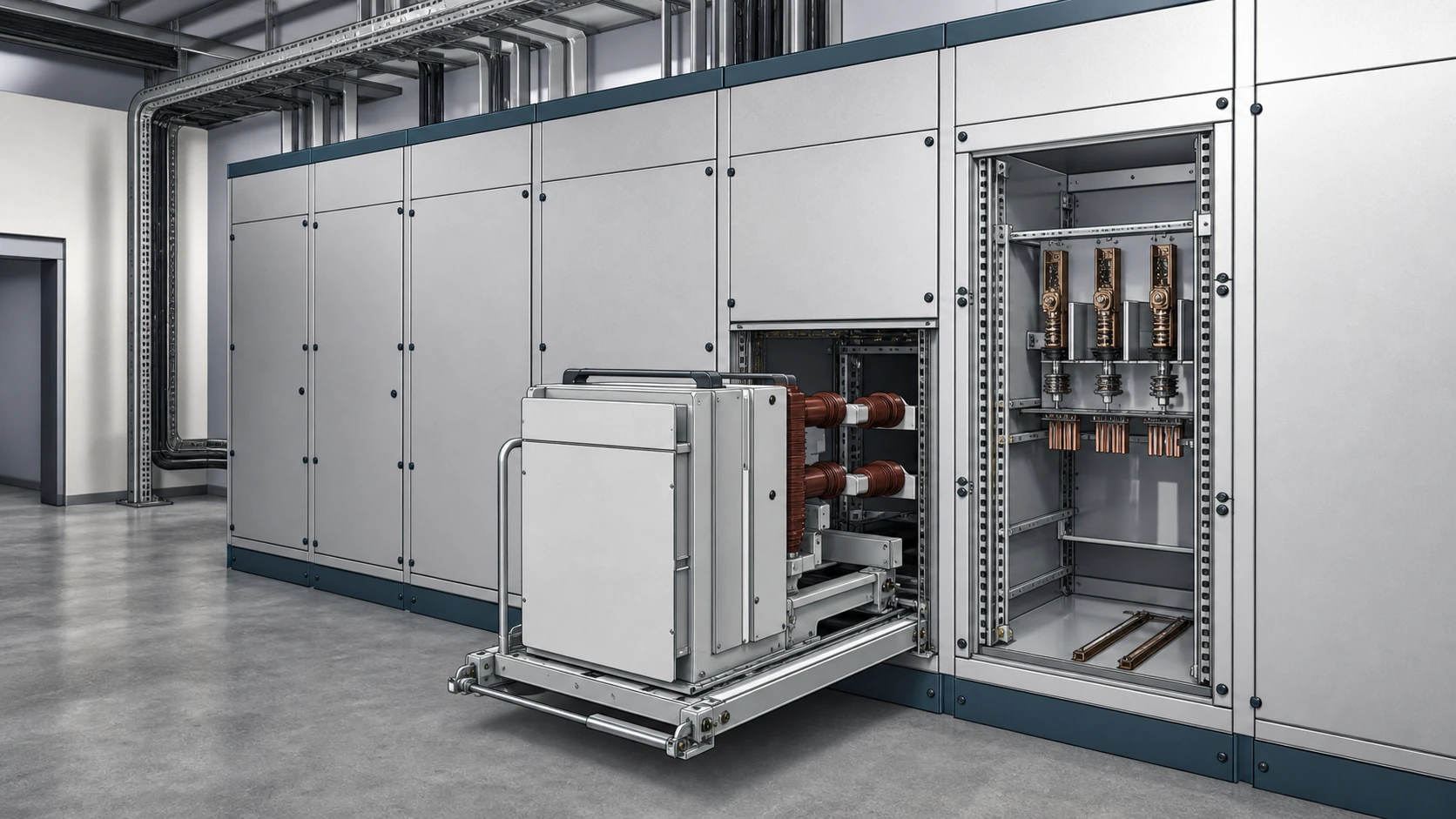
IEC 62271-100 governs the vacuum circuit breaker's interrupting performance, and IEC 62271-200 governs the metal-enclosed switchgear assembly in which it operates. The breaker's type-test certificate confirms its rated voltage, short-circuit breaking capacity, and mechanical endurance. The switchgear assembly's type-test certificate confirms the combination of breaker, enclosure, bus, and interfaces tested together. A replacement breaker that was not included in the original switchgear type test may require a re-verification or a documented engineering assessment to confirm that the assembly still meets the rated internal-arc, dielectric, and temperature-rise performance. This is the single most consequential evidence boundary in a replacement review: the breaker alone does not certify the assembly.
Schneider Electric's fixed-versus-withdrawable comparison frames this distinction within the switchgear application context, noting that the arrangement choice is a switchgear-level decision, not merely a breaker-level one. This framing reinforces a practical rule: replacement evidence must include both the breaker datasheet and the switchgear manufacturer's compatibility or integration documentation.
Replacement Review Workflow
The following sequence consolidates the selection, verification, and procurement-readiness steps into a single pass. It applies whether the replacement is like-for-like or a cross-arrangement change.
1. Record the existing breaker's nameplate data: manufacturer, type designation, rated voltage, rated current, rated short-circuit breaking current, and serial or production number.
2. Record the switchgear's nameplate data separately. Confirm the switchgear type-test standard and the original breaker model referenced in the assembly certificate.
3. Identify the mounting arrangement — fixed or drawout — and document the five interface categories from Schneider Electric's integration framework: mechanical fixation, earthing, medium-voltage electrical, auxiliary-circuit, and racking.
4. For each interface category, capture as-built dimensions, connector types, contact configurations, and any adapter hardware currently installed.
5. If a cross-arrangement change is under consideration, flag it as a switchgear modification project, not a breaker replacement project. The evidence scope expands to include structural, thermal, dielectric, and arc-containment re-assessment of the enclosure.
6. Compile a replacement-candidate shortlist. For each candidate, request from the manufacturer an integration guide or compatibility statement that addresses all five interface categories against the specific switchgear type.
7. Confirm that the candidate breaker's type-test certificate covers the rated values required by the installation's protection study. Do not assume that a higher-rated breaker is automatically compatible; higher ratings can mean larger physical dimensions or different contact geometries.
8. Prepare the RFQ package: existing nameplate data, interface evidence, switchgear type-test reference, and any site constraints (access width, lifting height, cable-entry direction).
Installation Risks and Failure Modes to Verify Before Procurement
Dimensional mismatch is the most common failure mode. A drawout breaker that is a few millimetres too wide, too deep, or offset in rail pitch will bind during racking and can damage the primary plug-in contacts or the racking mechanism. A fixed breaker with a different bolt pattern may require field-drilled mounting holes, which compromises the enclosure's arc-containment rating.
Auxiliary-circuit mismatch is the most dangerous failure mode. If the replacement breaker's auxiliary plug has a different pin count or assignment, protection trip circuits can be left open. The breaker appears to function normally during commissioning but fails to trip on the first fault. Verification of auxiliary-circuit continuity end-to-end — from the protection relay output through the auxiliary plug to the trip coil — is a non-negotiable commissioning check, and the data to confirm it must be available before the RFQ.
Contact-pressure degradation applies specifically to drawout arrangements. If the replacement breaker's moving primary contacts do not deliver the design contact force against the switchgear's stationary tulip contacts, the joint resistance rises, causing localised heating under load. This condition is invisible until a thermal survey or a temperature-rise test detects it. The manufacturer's integration documentation should specify the required contact force or reference a mating-contact part number.
Earthing-path discontinuity can occur in either arrangement if the replacement breaker's earth terminal or automatic earth contact does not align with the switchgear's earth bus. The result is a floating breaker frame, which creates a touch-potential hazard. The earthing interface dimension and engagement force belong in the RFQ checklist.
Model-specific approved procedures govern all live installation, racking, switching, adjustment, and commissioning actions. The evidence gathered during the replacement review informs what those procedures must address, but the review itself does not substitute for them.
Data Checklist for the RFQ
Before contacting a breaker supplier, confirm that the following data is assembled. Missing items stall the quotation or, worse, lead to a delivered breaker that cannot be integrated.
- Switchgear manufacturer, type, and type-test certificate reference
- Existing breaker manufacturer, type designation, and rated values
- Mounting arrangement: fixed or drawout
- Compartment internal dimensions (width, height, depth) and access clearance
- Primary connection geometry: bus bar size, spacing, phase sequence, and connection method (bolted or plug-in)
- Auxiliary-circuit connector type, pin count, pin assignment, and voltage
- Earthing interface type and position
- Racking-mechanism specification (drawout only): travel distance, interlock positions, shutter type
- Site constraints: transport access, lifting capacity, ambient temperature, altitude
- Protection relay model and trip-circuit configuration, including any communication-bus requirements
This checklist maps directly to the five integration categories documented in Schneider Electric's EvoPacT HVX-O integration guide, expanded with the site and protection data that a breaker supplier needs to confirm fit.
FAQ
What is the main difference between a fixed and a drawout vacuum circuit breaker?
The vacuum interrupting technology is the same. The difference is in how the breaker connects to the switchgear: a fixed breaker is bolted in place with hardwired connections, while a drawout breaker sits on a racking mechanism with plug-in primary and auxiliary contacts, allowing it to be moved between connected, test, and disconnected positions without unbolting anything.
What is the risk of replacing a drawout breaker with a different manufacturer's model?
The primary risk is interface mismatch across five categories: mechanical fixation and rail geometry, medium-voltage plug-in contact dimensions and contact pressure, auxiliary-circuit plug pin assignment, earthing contact alignment, and racking-mechanism compatibility. Any single mismatch can prevent safe operation. A manufacturer integration statement specific to the target switchgear type is needed before procurement.
What is required to verify that a replacement breaker is compatible with existing switchgear?
Compatibility verification requires both the breaker's own type-test certificate and the switchgear manufacturer's integration or compatibility documentation confirming that the specific breaker model has been validated in that switchgear assembly. The breaker type test alone does not certify the assembled combination for internal-arc, dielectric, or temperature-rise performance.
What is the most dangerous failure mode in a vacuum circuit breaker replacement?
Auxiliary-circuit mismatch is the most dangerous failure mode because it can leave the protection trip circuit open without any visible indication. The breaker appears functional during normal operation and manual testing but fails to trip automatically on a fault, which can lead to sustained arcing and catastrophic switchgear failure.
What is the evidence boundary between a breaker replacement and a switchgear modification?
When the replacement stays within the same mounting arrangement and the new breaker's interfaces match the existing compartment, it is a breaker replacement. When the mounting arrangement changes — fixed to drawout or drawout to fixed — or when the compartment must be structurally modified to accept the new breaker, the project scope shifts to a switchgear modification, which triggers re-assessment of the enclosure's arc-containment, dielectric, and thermal ratings under the applicable switchgear assembly standard.

