

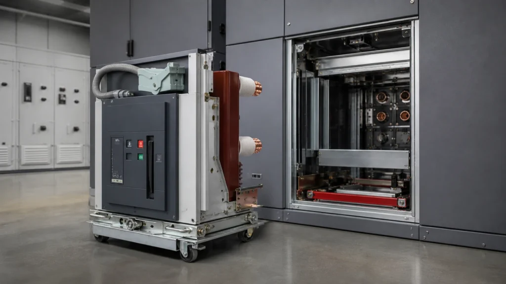
Quick Takeaway
- Confirm the project duty and applicable requirements for Vacuum Circuit Breakers before selection or service work.
- Use recorded inspection and test evidence instead of unsupported assumptions.
- Keep the final acceptance, maintenance, and handover documents with the equipment record.
Before requesting a quote for a vacuum circuit breaker (VCB) replacement, gather complete nameplate data, system operating parameters, and interface documentation for the existing unit. This information determines whether a candidate replacement is technically compatible and allows a supplier to scope the work accurately. Skipping any category typically results in clarification delays, incorrect proposals, or field problems during installation.
Why Replacement Is Not a Simple Swap
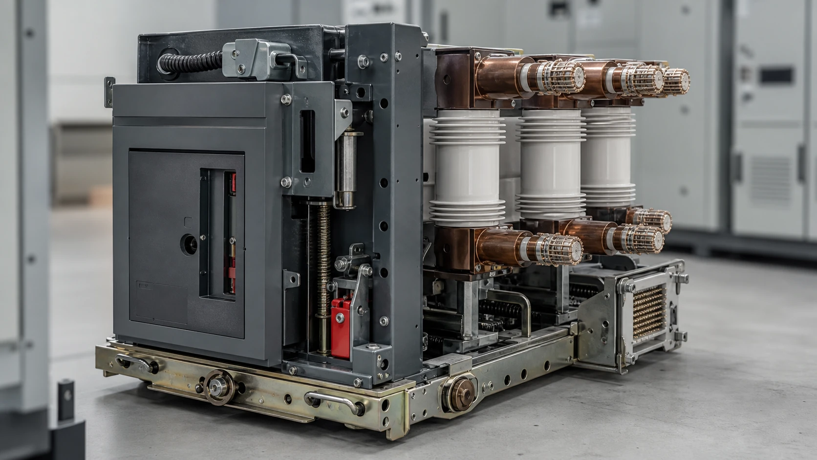
A vacuum circuit breaker is a rated assembly: its interrupting medium, mechanical operating mechanism, control interfaces, and protection relay connections form a system. IEC 62271-100 applies to three-phase AC circuit breakers for indoor or outdoor installation on systems above 1 kV and defines the performance envelope — rated voltage, rated normal current, rated short-circuit breaking current, and associated duties — within which any replacement must sit. IEC 62271-1 provides the common specifications for AC switchgear and controlgear above 1 kV and ties the review explicitly to the applicable equipment documentation and service conditions, not to nominal ratings alone.
This means a replacement VCB with matching voltage and current ratings on its nameplate is a starting point, not a conclusion. Rated values must be confirmed against actual service conditions, and mechanical, control, and protection interfaces must be verified separately. The vacuum circuit breaker product context can help define the relevant equipment family, but it cannot replace model- and panel-specific evidence. A replacement that fits the cubicle but uses a different racking mechanism, a different trip coil voltage, or a different auxiliary contact arrangement can disable protection functions or prevent the breaker from closing under auto-reclose.
Nameplate and Ratings Data to Collect
Pull the existing breaker's nameplate before contacting any supplier. The minimum dataset is:
- **Manufacturer, model designation, and serial number** — needed to locate original drawings and to identify the operating mechanism family
- **Rated voltage (Ur)** and **rated insulation level (power-frequency and lightning impulse withstand)** — confirms the voltage class
- **Rated normal current (Ir)** — continuous current-carrying capacity
- **Rated short-circuit breaking current (Isc)** and **rated short-circuit making current** — defines interrupting duty; confirm these against the current fault level study for the installation, not just the original design value
- **Rated operating sequence** — typically O – 0.3s – CO – 3 min – CO or similar, per the equipment documentation
- **Rated frequency**
- **Control voltage(s)** for closing coil, trip coil(s), and spring-charging motor
- **Auxiliary contact configuration** — number, type (NO/NF), and current rating
- **Mechanical endurance class** — relevant where high operation counts are expected
If the nameplate is damaged or missing, the original type test certificate or factory test report is the next source. Do not rely on peer equipment at the same site without confirming that ratings were not revised between procurement batches.
Switchgear Panel and Physical Interface Data
The replacement breaker must physically fit and functionally mate with the existing switchgear panel. Collect:
- **Panel manufacturer, cubicle type, and panel serial number or drawing reference** — VCBs are frequently panel-specific; many manufacturers offer only designated replacement types for their own cubicles
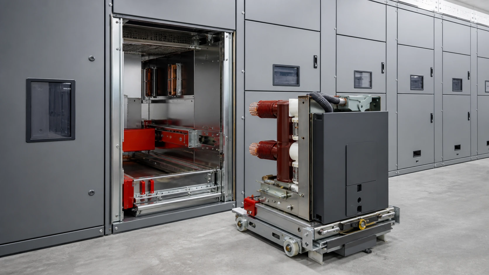
- **Withdrawable or fixed mounting** — if withdrawable, confirm the racking system, truck dimensions, and primary disconnect spout arrangement against the available chassis truck and racking-system information
- **Primary circuit connection geometry** — busbar arrangement (top/bottom, front/rear), phase spacing, contact pad dimensions, and stab dimensions for withdrawable units
- **Secondary (control) connector type and pin assignment** — multi-pin plugs vary between manufacturers and generations; the secondary connector and control-component context is useful vocabulary, but pin-assignment drawings are required
- **Breaker overall dimensions and weight** — clearance to live parts, floor loading, and handling access all depend on this
- **Earthing switch interlocking arrangements** — mechanical and electrical interlocks with the panel earthing switch must be preserved in the replacement
Operating Mechanism and Control Circuit Requirements
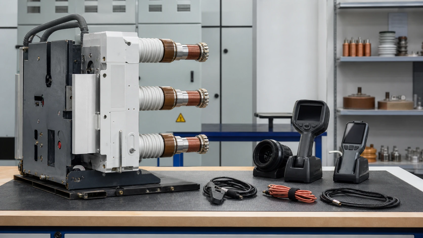
The operating mechanism is the most common source of hidden incompatibility. Collect:
- **Mechanism type** — spring-stored energy (manual or motor-charged), magnetic actuator, or pneumatic; the replacement mechanism family must match the panel's control and indication wiring
- **Closing coil voltage and current duty** — continuous or pulsed; some panels supply closing power for a timed pulse only
- **Trip coil voltage(s)** — single or dual trip coils; confirm whether the protection relay outputs are voltage-sourced or current-sourced
- **Anti-pumping feature** — confirm whether anti-pumping logic resides in the breaker mechanism or in the panel control circuit; relocating it introduces new coordination risk
- **Spring-charged status indication** — contact type and wiring destination in the panel
- **Manual trip and close capability** — required for local test and commissioning; confirm the panel door cutout and push-button arrangement matches
- **Motor supply voltage and phase** for motorised-charge mechanisms
Do not assume that a replacement from the same manufacturer as the panel will have identical control wiring without drawing verification. Product generations change coil ratings and contact arrangements.
Protection and Secondary System Interfaces
Protection relay compatibility is outside the scope of a VCB replacement quote, but the data collected here determines whether secondary circuit changes are required and who scopes them:
- **Current transformer (CT) configuration** — number of CTs, cores per CT, ratio(s), accuracy class, and burden; confirm whether CTs are integral to the breaker or mounted separately in the panel
- **Voltage transformer (VT) arrangement** — if VT is integral to the breaker truck, confirm metering and protection burdens
- **Protection relay type and firmware version** — relevant because some relays use breaker-specific binary input schemes or communicate with the mechanism directly (IEC 61850 GOOSE, for example)
- **Trip circuit supervision wiring** — many installations use TC supervision relays wired through auxiliary contacts; the new contact arrangement must maintain continuity of supervision
- **Remote indication and SCADA points** — bay controller or RTU input lists that depend on auxiliary contact states
This data does not define protection settings — model-specific approved procedures govern those actions — but it does define the scope boundary between a mechanical replacement and a protection system modification.
Site and Service Condition Data
IEC 62271-1 ties specification compliance to actual service conditions. Collect:
- **Altitude** — standard ratings apply to installations up to 1000 m; derating applies above that
- **Ambient temperature range** — maximum and minimum; relevant for mechanism lubrication performance and control voltage ranges
- **Humidity and pollution level** — IEC pollution degree classification for indoor vs. outdoor, coastal, or industrial environments
- **Seismic zone** — if applicable; some installations require seismic qualification of replacement equipment
- **Available fault level at the installation point** — from the current system fault study, not the original design study; fault levels change as networks evolve, and a replacement rated to the original study value may be underrated for current conditions
- **Operational duty** — expected switching frequency, capacitor bank or motor switching duty if applicable; these impose additional type test requirements beyond standard short-circuit duty
Documentation Package to Request with the Quote
A complete quote response should include, at minimum:
- Replacement type test certificate confirming compliance with IEC 62271-100 for the rated values relevant to the installation
- Dimensional and interface drawings confirming physical fit in the existing panel
- Secondary wiring diagram or interface drawing for control circuit comparison against existing panel drawings
- Outline of any modifications required to the panel cubicle or control circuits
- Recommended spare parts list for the replacement mechanism
- Installation and commissioning scope statement — model-specific approved procedures govern those actions, and the supplier should confirm who provides them
If the supplier cannot provide type test evidence or panel compatibility documentation, treat that as a procurement risk item before committing.
When the evidence package is ready, send the replacement RFQ to Reeuini's engineering team for a drawing-led scope review. A quotation does not replace the project team's approval of duty, interfaces, or site procedures.
Checklist for Condition Assessment of the Existing Breaker
Before proceeding with replacement, confirm that replacement is actually warranted. A condition assessment may find that the existing breaker is serviceable with maintenance. Relevant questions for the asset owner:
- What is the recorded operation count, and how does it compare with the manufacturer's mechanical and electrical endurance rating?
- Is there documented evidence of vacuum interrupter degradation (dielectric test results, contact wear measurements)?
- Are there open corrective maintenance items — mechanism faults, auxiliary contact failures, coil resistance out of tolerance?
- What is the remaining expected service life of the panel itself? Replacing a VCB in a panel scheduled for replacement within five years may not be economical.
- Does the site have access to the original manufacturer's service capability, or has that been withdrawn?
These questions do not change the information required for a quote, but they establish the business case that justifies replacement versus maintenance.
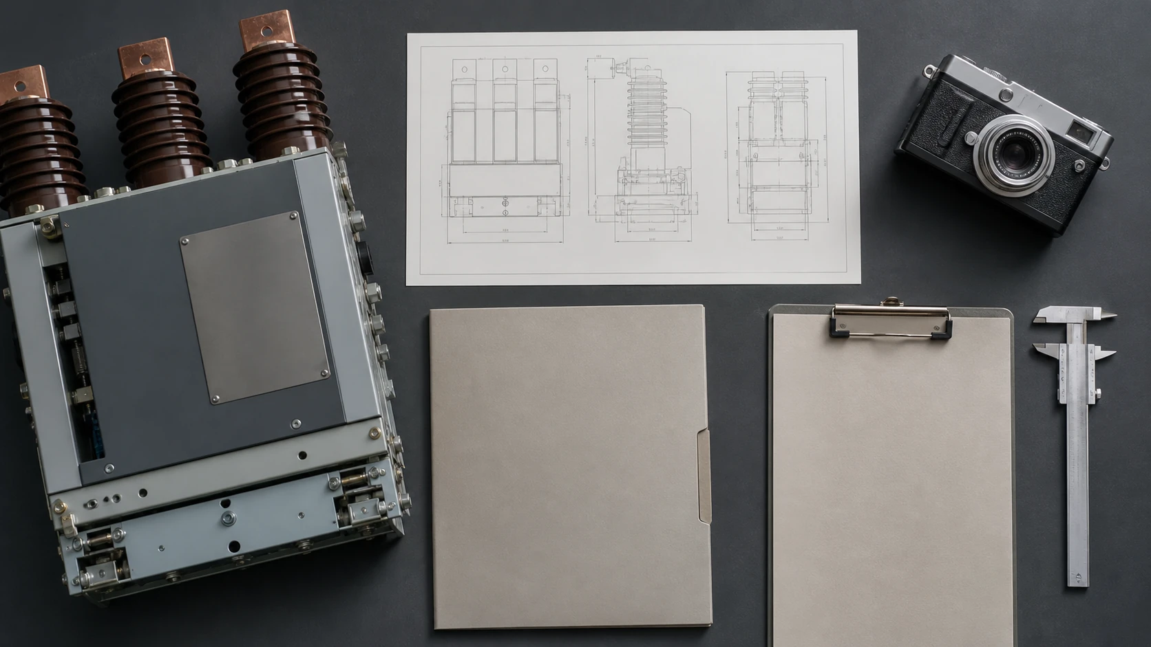
Pre-RFQ Information Checklist: Standards and Acceptance Status
| Item | Required data | Status | Evidence reference |
|---|---|---|---|
| Nameplate ratings | Ur, Ir, Isc, rated sequence, serial number | ☐ Collected | Nameplate photograph or factory test report |
| Insulation level | Power-frequency and LI withstand values | ☐ Collected | Nameplate or type test certificate |
| Control voltages | Closing coil, trip coil(s), motor supply | ☐ Collected | Panel schematic drawing |
| Auxiliary contacts | Configuration, current rating, pin assignment | ☐ Collected | Secondary wiring diagram |
| Physical dimensions | Overall dimensions, weight, racking dimensions | ☐ Collected | Manufacturer dimensional drawing |
| Panel interface | Cubicle type, spout geometry, secondary connector | ☐ Collected | Panel GA drawing and wiring diagram |
| CT/VT data | Ratio, class, burden, core count | ☐ Collected | Protection relay study or panel drawing |
| Fault level confirmation | Current system fault study value at installation point | ☐ Confirmed | Protection coordination study (dated) |
| Service conditions | Altitude, ambient range, pollution level | ☐ Confirmed | Site survey or installation record |
| IEC 62271-100 type test | Replacement unit test certificate for relevant ratings | ☐ Requested | Supplier type test certificate |
| IEC 62271-1 service conditions | Derating or special requirements confirmed | ☐ Reviewed | Equipment documentation and service records |
| Operation count vs. endurance | Recorded count vs. rated mechanical/electrical endurance | ☐ Reviewed | Maintenance log |
| Protection relay compatibility | Binary input scheme, GOOSE links, TC supervision | ☐ Reviewed | Protection relay documentation |
| Supplier installation scope | Approved procedures availability confirmed | ☐ Confirmed | Supplier scope statement |
—
FAQ
What is a vacuum circuit breaker and how does it differ from other medium-voltage breakers?
A vacuum circuit breaker interrupts fault and load current by separating contacts inside a sealed vacuum interrupter bottle, where the very low pressure suppresses the arc almost immediately after current zero. The main practical differences from SF₆ and air-blast designs are that the interrupting medium requires no gas handling or pressure monitoring, the interrupter is a sealed unit that degrades slowly rather than requiring regular gas top-up, and the operating mechanism is typically a spring-stored-energy type suited to high-reliability indoor switchgear. For replacement purposes the relevant consequence is that vacuum interrupter condition must be verified by dielectric testing rather than by gas analysis.
What is the vacuum circuit breaker replacement checklist and why does it matter before requesting a quote?
The replacement checklist is a structured list of technical, physical, and documentary information that must be assembled before a supplier can produce a technically valid and comparable quotation. It matters because VCBs are rated assemblies with interlocking mechanical, electrical, and protection interfaces: a quote produced without complete interface data is likely to omit panel modification costs, secondary circuit changes, or protection relay adjustments that only become visible during installation. Gathering the checklist data upfront compresses the clarification cycle, reduces the risk of field incompatibility, and gives the asset owner a clear scope boundary between breaker supply and associated works.
What is IEC 62271-100 and how does it apply to a replacement decision?
IEC 62271-100 is the IEC standard that applies to three-phase AC circuit breakers for indoor or outdoor installation on systems above 1 kV. In a replacement context it sets the product scope boundary: a replacement VCB must hold a valid type test certificate demonstrating compliance with the standard for the rated voltage, current, and interrupting duty relevant to the installation. The standard defines rated operating sequences, type test duties, and routine test requirements. It does not govern the physical or control interface compatibility between the replacement breaker and the existing panel — those are verified separately against panel documentation and the data collected in the checklist above.
What is IEC 62271-1 and what does it add to a replacement review?
IEC 62271-1 provides the common specifications for AC switchgear and controlgear above 1 kV. Its significance for replacement is that it ties compliance to actual service conditions, not just nameplate ratings. A replacement review must therefore remain tied to the applicable equipment documentation and service conditions — meaning that altitude, ambient temperature, humidity, and pollution level at the installation site must be confirmed and checked against the replacement unit's ratings, and any required derating must be captured in the specification before the RFQ is issued.
What is the difference between mechanical and electrical endurance ratings for a VCB?
Mechanical endurance is the number of open-close operations the mechanism is designed to perform without maintenance or parts replacement, regardless of whether current was being interrupted. Electrical endurance is the number of rated short-circuit or load interruptions the vacuum interrupter is designed to perform before contact erosion reaches the end-of-life criterion. Both counters run simultaneously during service. A breaker that has reached its electrical endurance limit on a feeder with frequent fault clearances may still have most of its mechanical endurance remaining; the interrupter and mechanism are separate wear items. Collecting operation count data and comparing it to both endurance ratings is part of the condition assessment that determines whether replacement is justified.
What is the role of the panel cubicle drawing in a VCB replacement?
The panel cubicle general arrangement drawing and associated wiring diagrams are the primary source for physical interface verification. They define the racking dimensions and disconnect spout geometry that the replacement breaker truck must match, the secondary connector type and pin assignment that the replacement's control plug must be compatible with, the interlocking arrangements between the breaker and any panel earthing switch, and the control circuit scheme that determines whether the replacement mechanism's coil ratings and auxiliary contact arrangement are directly compatible or require panel-side modifications. Without these drawings, a supplier is working from nominal dimensions only, and interface problems typically surface during site installation rather than during engineering review.

