

Switchgear Insulation Components
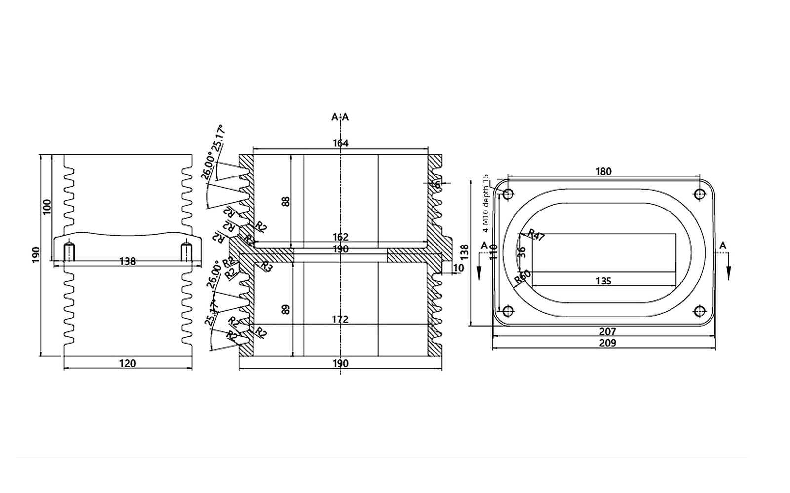
Compare 56 wall bushings, contact boxes, post insulators, voltage sensors, GIS bushings and insulation covers for new MV switchgear, replacement and retrofit projects. Each product record includes a dimensional drawing for interface checks.
Medium-Voltage Switchgear Insulation Components by Type and Voltage
Filter 56 records by component type, rated voltage, current where stated, model and key dimensions. Open a product to check its dimensional drawing before preparing an RFQ.
Product Dimensions & Drawing
For quotation and fit check
Send the switchgear type, rated voltage and current where applicable, quantity, existing part marking, installed photos and marked interface dimensions. For replacement work, include the available project drawing.
Full-size dimensional drawing
How to Select MV Switchgear Insulation Components by Rated Voltage and Dimensions
For a new panel, replacement or retrofit, first match the electrical rating and component function. Then compare the installed mounting and mating dimensions with the drawing for the exact model.
- Rated voltage and current
- Specify the rated or system voltage, rated current where applicable, switchgear type and insulation medium. Identify whether the equipment is indoor AIS, GIS or SF6-free GIS.
- Mounting and mating dimensions
- Measure the overall envelope, opening size, flange or base and mounting-hole pattern. Also record the conductor, contact-arm, cable or terminal interface, connection direction, phase spacing and available clearance.
- Switchgear identity and project scope
- State the switchgear type and whether the project is a new panel, replacement or retrofit. For replacement work, include the existing part model or marking, installed photos, drawing, quantity and any parts that must remain unchanged.
Types of Switchgear Insulation Components and Their Applications
Identify the component by its installed function before comparing models. Each group below lists the electrical rating, mounting geometry and mating interface to include in a technical enquiry.
01Wall BushingsPanel-wall and compartment-passage insulation.+
Match the wall opening, flange and conductor passage
Use a wall bushing where an insulated conductor passes through a panel, partition or compartment boundary. Select from the installed opening and mating geometry, not from the outside profile alone.
- Used for
- Insulated conductor passage through a defined cabinet wall or partition.
- Specify for quotation
- Rated voltage; overall length; opening and conductor-window geometry; flange or base dimensions; mounting-hole pattern; connection direction and clearance.
- Do not substitute
- A wall bushing is not a contact box, post insulator or GIS cable-interface bushing.
02Contact BoxesFixed-contact-zone insulation and support.+
Verify the fixed-contact and cabinet-depth interface
Contact boxes insulate and position the fixed-contact area in withdrawable switchgear. Similar red epoxy parts may have different contact-arm, base and cabinet-depth requirements.
- Used for
- Insulation and positioning around the fixed-contact interface.
- Specify for quotation
- Rated voltage and current; contact-arm or conductor interface; base footprint; mounting holes; installed depth; phase spacing and cabinet arrangement.
- Do not substitute
- Do not replace a contact box with a wall bushing or a visually similar combined insulator.
03Switchgear InsulatorsBusbar, mechanism and assembly support insulation.+
Confirm the support task, inserts and installed height
Post and combined insulators must be selected for the actual mechanical support and electrical arrangement. Height variants and insert patterns must match the model-specific drawing.
- Used for
- Insulated support for a busbar, mechanism or combined switchgear assembly.
- Specify for quotation
- Rated voltage; support function; overall height and diameter; upper and lower inserts or threads; mounting orientation and adjacent clearances.
- Do not substitute
- A voltage sensor can resemble a post insulator but performs a different electrical function.
04Voltage SensorsVoltage-presence or sensing position.+
Match the sensor body, terminals and connected circuit
Choose a voltage sensor where the installed part provides voltage measurement, indication or an associated circuit input. Confirm both the mechanical interface and the electrical output or connected circuit.
- Used for
- Voltage measurement, voltage-presence indication or an associated circuit input.
- Specify for quotation
- Rated voltage; sensor model; body dimensions; terminal and output arrangement; mounting; earthing-switch application where stated; connected indication or protection device.
- Do not substitute
- A standard post insulator does not replace the voltage-measurement or indication function.
05GIS BushingsGIS cable, side-extension, coupling and inner-cone interfaces.+
Identify the GIS interface before comparing dimensions
GIS bushings use several distinct interface systems. First identify the equipment system and connection role, then compare the exact axial, flange and mating geometry.
- Used for
- Insulated GIS cable, extension, coupling, quick-connect or inner-cone interface.
- Specify for quotation
- GIS type; rated voltage and current where applicable; interface form; flange and axial dimensions; connection direction; mating part and approved project drawing.
- Do not substitute
- AIS wall bushings and generic cable-support parts are not automatic substitutes for a GIS bushing.
06Insulation CoversUpper and lower protective insulation around a matching assembly.+
Match the cover position and mating component
Upper and lower insulation covers are separately identifiable parts. Their geometry must match the component and cabinet arrangement they protect.
- Used for
- Protective insulation around the designated upper or lower assembly position.
- Specify for quotation
- Upper or lower installation position; mating component; mounting points; local clearances; adjacent conductors and complete cabinet arrangement.
- Do not substitute
- An upper cover and a lower cover are not interchangeable, and neither replaces a primary bushing or support insulator.
Switchgear Insulation Component Dimensions and Drawing Checks
Check the dimensional drawing for the exact model before purchase. For replacement work, compare the five items below with field measurements and the existing mounting interface.
Five drawing checks before purchase
- Overall envelope
Compare the total height or length and maximum diameter with the available cabinet space.
- Mounting interface
Confirm the flange or base dimensions, opening geometry and fixing-hole pattern.
- Mating interface
Check the conductor window, contact arm, cable, terminal, insert or thread geometry.
- Direction and clearance
Verify mounting orientation, connection direction, phase spacing and adjacent clearances.
- Drawing identity
Match the model, electrical variant, units and drawing revision to the ordered record.
Switchgear Insulation Component Application and Compatibility Guide
Choose the component family from its installed function, then match the rated values, mounting dimensions and mating interface. Similar appearance does not establish interchangeability.
| Installed application | Component family | Selection data to match |
|---|---|---|
| Panel wall or compartment passage | Wall BushingsInsulated conductor passage through an AIS cabinet wall or partition. | Match these dataRated voltage, opening geometry, flange, mounting-hole pattern, conductor window, overall length and connection direction. |
| Fixed-contact compartment interface | Contact BoxesInsulation and support around the fixed-contact zone. | Match these dataVoltage and current duty, contact-arm or conductor interface, base dimensions, installed depth, phase layout and cabinet clearance. |
| Busbar, mechanism or assembly support | Switchgear InsulatorsPost or combined insulation selected for the actual support task. | Match these dataRated voltage, installed height, body diameter, insert or thread pattern, mounting orientation and mechanical support arrangement. |
| Voltage-presence or sensing point | Voltage SensorsSensor body and terminals matched to the connected indication function. | Match these dataRated voltage, terminal and output arrangement, connected device, body dimensions, mounting and earthing-switch application where stated. |
| GIS cable, side-extension, coupling or inner-cone interface | GIS BushingsGIS interface selected by equipment system and connection form. | Match these dataGIS type, interface form, voltage and current where applicable, flange and axial dimensions, mating component and approved drawing. |
| Upper or lower protective insulation position | Insulation CoversProtective cover matched to the designated mating assembly. | Match these dataUpper or lower position, mating component, mounting points, local clearances, adjacent conductors and complete cabinet arrangement. |
Contact-arm sleeves, silicone boots and cable fixers serve different insulation or cable-support functions. Specify them separately rather than treating them as substitutes for wall bushings, contact boxes, post insulators, voltage sensors or GIS bushings.
Switchgear Insulation Component RFQ and Replacement Checklist
Send the information below so engineering and procurement can compare the same electrical, mechanical and commercial scope. State whether the request is for a new panel, replacement or retrofit.
Switchgear Insulation Components: Selection, Replacement and Compatibility FAQs
Answers for engineers and professional buyers identifying replacement parts, checking interchangeability and preparing a complete technical enquiry.
What information is required to identify a replacement switchgear insulation component?
Start with the switchgear type designation, serial number and year of manufacture where available. Add the existing part model or marking, rated voltage and current, overall and mounting dimensions, hole pattern or interface type, installed photos, drawing revision, quantity and any parts that must remain unchanged.
What is the difference between a switchgear wall bushing, contact box and post insulator?
A wall bushing insulates a conductor where it passes through a panel or compartment wall. A contact box supports and insulates the fixed-contact area in withdrawable switchgear. A post insulator provides mechanical support and electrical insulation for a busbar or assembly. Select the component by this installed function before comparing its dimensions.
Are switchgear insulation components with the same voltage rating interchangeable?
No. The same voltage rating does not confirm the same installed function, rated current, mounting-hole pattern, overall dimensions, conductor or cable interface, terminal arrangement or clearance. Compare the exact model drawing and mating interface before approving a substitute.
Can a voltage sensor be replaced by a standard post insulator?
Not automatically. Some voltage sensors are designed to provide post-insulator mechanical support, but they also serve voltage measurement or indication. A standard post insulator does not provide that electrical function. Match the sensor model, rated voltage, output and terminal arrangement, connected indicator or protection device, dimensions and mounting before replacement.
How do I select a GIS bushing or separable connector interface?
Identify the GIS equipment and bushing interface system first, including Type B, C or F and inner-cone or outer-cone construction where applicable. Then match the cable, busbar or coupling role, rated voltage and current, mating component, conductor or cable dimensions, flange and axial dimensions and approved project drawing.