

MV Switchgear Auxiliary Components

Source SF6 pressure gauges and gas-density monitors, voltage presence indicators, electromagnetic locks, anti-condensation heaters and transfer trolleys for medium-voltage switchgear. Compare model specifications, mounting interfaces and drawings for new panels, replacement parts and retrofit projects.

Request an auxiliary components quote

MV Switchgear Auxiliary Components for Monitoring, Interlocking and Cabinet Control

Browse five product groups for gas monitoring, voltage indication, switchgear door interlocking, cabinet heating and equipment handling. Open a card to compare model-specific technical data, installation dimensions and engineering drawings on this page.


How to Select MV Switchgear Auxiliary Components for New Panels and Replacement

Start with the component function, then match its electrical duty and physical interface to the switchgear. Supplying these three groups of information helps engineering identify the right model and helps purchasing compare quotations on the same scope.

01 Component function and electrical requirements
Identify gas monitoring, voltage indication, electromagnetic interlocking, anti-condensation heating or external transfer duty. State the system voltage, auxiliary AC/DC supply, required contacts and control or release logic where applicable.

02 Mounting, cut-out and cabinet interface
Provide the pressure connection, front-panel cut-out, door-lock mounting, heater footprint or trolley interface. Include mounting-hole positions, clearances, cabinet width and the wiring or installation drawing.

03 Existing model and project requirements
For a replacement, send the complete existing model, switchgear nameplate, installed photographs and measured dimensions. Include quantity, project location and whether the requirement is for a new panel, spare, replacement or retrofit.
Switchgear installation detailsUse the cabinet drawing and installed photographs to confirm mounting, panel cut-out, connection, wiring and clearance before the replacement model is approved.

MV Switchgear Auxiliary Components Selection Guide

Open a product group to see which ratings, dimensions, wiring details and cabinet interfaces must be matched before a model can be quoted for a new panel or replacement.

01Gas pressure and density monitoringPressure indication and density monitoring for sealed GIS and RMU gas compartments.

Choose an SF6 pressure gauge or gas density monitor by function

Use a pressure gauge for local indication. Use a temperature-compensated gas density monitor when the application also requires alarm or switching contacts. Confirm the gas or gas mixture, calibrated range, process connection, ambient conditions and contact setpoints.

Available models
60N-Z-L1-G and 60N-Z-L1-K pressure gauges; MJ SF6 gas-density relay family.
Gas and operating requirements
State the switchgear type, gas or gas mixture, filling or operating range, ambient conditions and required alarm or switching points.
Mechanical and electrical interface
Provide the process connection, mounting direction, dial orientation and contact wiring where applicable.
02Voltage presence indicationPanel-mounted voltage indication and related interlock functions.

Select a voltage indicator by system voltage, panel cut-out and circuit function

Match the exact function—voltage presence indication, phase-comparison access or relay interlock—with the capacitive interface, panel opening, auxiliary supply and terminal wiring. A similar front panel does not confirm electrical or mechanical compatibility.

Available models
DXN8, DXN8-12/T8S and L-6 families.
Panel interface
54 × 32 mm, 92 × 44 mm and 102 × 72 mm panel formats are available across the listed families; use the drawing for the exact model.
Electrical requirements
State the rated system voltage, phase or test-point arrangement, indication or interlock function, auxiliary supply and wiring.
03Electromagnetic interlockingDoor-access and operating-sequence interlocking for switchgear panels.

Match the electromagnetic lock voltage, direction and release logic

Confirm the complete DSN model, AC/DC supply, left- or right-hand assembly, energized or de-energized release logic, door cut-out, mounting holes, bolt travel, terminals and cabinet linkage.

Available models
DSN-AMY, DSN-BMY and DSN-I/Y types.
Mechanical interface
State the door or panel opening, mounting-hole pattern, orientation, lock direction and cabinet linkage.
Electrical interlock
State the auxiliary voltage, terminal arrangement, release logic and required position or status contacts.
04Cabinet environmental controlAnti-condensation heating, temperature-humidity control and cabinet lighting.

Select switchgear heaters by supply, wattage and cabinet conditions

Choose the heater together with the thermostat or humidity controller. Match the auxiliary supply, heating duty, cabinet volume, site conditions, ventilation, mounting space, clearances and terminal protection.

Available components
DJR-S 100 W aluminium-fin heater, temperature-humidity controllers and cabinet lights.
Heating duty
The aluminium-fin heater family covers 25–200 W; choose the output for the cabinet design and anti-condensation requirement.
Control and mounting
State the supply, mounting space, cabinet volume, ventilation and the required thermostat or humidistat control scheme.
05Transfer trolleysExternal handling equipment for moving switchgear devices to and from the panel.

Choose a transfer trolley by cabinet width, load and transfer height

Match the trolley to the switchgear and device being handled. Confirm cabinet width, equipment mass, required transfer height, travel path, locating interface and manual, electric or hydraulic operating method.

Available model
REZC-3 simple-type transfer trolley.
Mechanical fit
For 12/24 kV applications, cabinet widths of 650 mm, 800 mm and 1000 mm are listed with a 300 kg holding load.
Handling duty
State the equipment mass, transfer height, travel arrangement and manual, electric or hydraulic operating requirement.

MV Switchgear Auxiliary Component Drawings, Dimensions and Wiring

Compare panel cut-outs, mounting dimensions, process connections, supply options and handling limits with the installed switchgear. Request the approved drawing for the exact model and revision before manufacturing or modification.

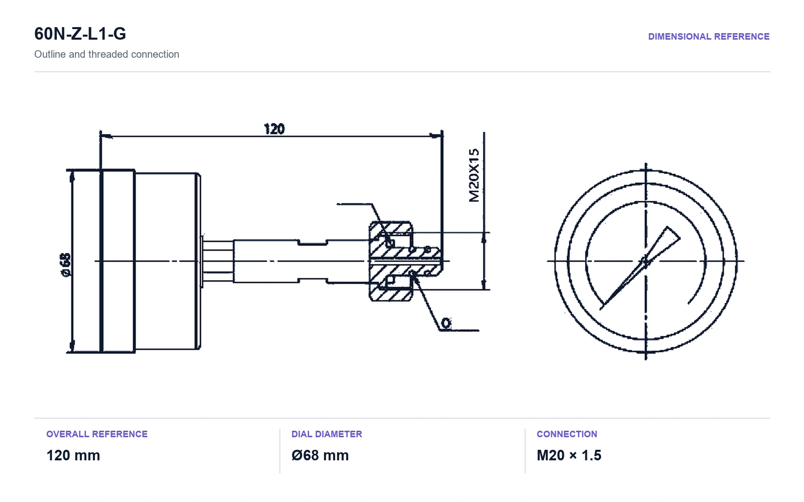
60N-Z-L1-G SF6 Pressure Gauge Dimensions

Check the Ø68 mm dial, 120 mm overall length and M20 × 1.5 process connection against the GIS or RMU gas compartment.

  • Overall length120 mm for model 60N-Z-L1-G.
  • Dial diameterØ68 mm.
  • Process connectionM20 × 1.5. Specify the required operating range with the enquiry.

DXN8-T Voltage Indicator Wiring and Panel Cut-out

Match the indication or interlock function, capacitance, auxiliary supply, terminal wiring and exact panel opening to the selected DXN model.

  • DXN8-T1 panel cut-out92 × 44 mm.
  • DXN8-T capacitance20 pF (50–110 pF); confirm the exact DXN8-T configuration.
  • Auxiliary supply optionsAC/DC 24 V, 48 V, 110 V and 220 V. Match the supply and wiring to the exact model.

DSN Electromagnetic Lock Door Cut-out and Supply Options

Available DSN documents show different cut-out and bolt-travel values. Confirm the left- or right-hand model, release logic and approved mechanical drawing before ordering.

  • Product-table door cut-out56 × 70 mm.
  • Engineering-drawing opening58 × 82 mm with two Ø6 mounting holes.
  • Electrical optionsAC/DC supply varies by DSN model; also confirm assembly direction, release logic and bolt travel.

DJR-S Switchgear Heater Dimensions and Mounting

Check heater wattage, AC/DC supply, footprint, mounting-hole span, controller arrangement and required clearance inside the cabinet.

  • Power range25–200 W for the aluminium-fin heater family.
  • Overall dimensions155 × 100 mm; confirm the selected wattage and enclosure form.
  • Mounting-hole span132 mm. Specify the supply and controller arrangement with the enquiry.

REZC-3 Switchgear Transfer Trolley Dimensions and Load

Match the trolley to the cabinet width, equipment mass, transfer height, travel path and locating interface before ordering.

  • Switchgear class12 / 24 kV applications.
  • Compatible cabinet widths650 mm, 800 mm and 1000 mm.
  • Holding load300 kg. This is external transfer equipment, not a switchgear handcart or chassis truck.

Replacement Compatibility Checklist for MV Switchgear Auxiliary Components

Before comparing quotations, verify the existing component, electrical requirements and mechanical interface. Use this checklist to identify the information that changes model selection for each auxiliary-component group.

MV switchgear auxiliary component replacement compatibility checklist
Component groupSend with your enquiryWhy it must match
Gas pressure or density monitoringSend with enquirySpecify the gas application, pressure or density range, process connection, dial direction and required alarm or switching contacts.Why it mattersLocal pressure indication and temperature-compensated density monitoring are not interchangeable; the range and connection must match.
Voltage presence indicationSend with enquirySpecify the system voltage, indication or interlock function, panel cut-out, wiring and auxiliary supply.Why it mattersA similar front plate can use a different cut-out, wiring arrangement or electrical function.
Electromagnetic interlockingSend with enquirySpecify the supply voltage, release logic, lock direction, door cut-out, mounting holes and cabinet linkage.Why it mattersThe lock must match both the physical door interface and the intended switchgear operating sequence.
Cabinet environmental controlSend with enquirySpecify the auxiliary supply, heater wattage, cabinet volume, mounting space and thermostat or humidistat control scheme.Why it mattersWattage alone does not define the mounting, supply or control arrangement needed for condensation control.
Transfer trolleySend with enquirySpecify the cabinet width, equipment mass, transfer height, travel arrangement and operating method.Why it mattersA transfer trolley is external handling equipment, not a switchgear handcart or circuit-breaker chassis truck.

How to Request a Quote for MV Switchgear Auxiliary Components

Send the product function, existing equipment details, electrical requirements, interface dimensions and commercial scope in one enquiry. This allows engineering to identify the model and purchasing to compare a clearly defined supply scope.

Documents and photographs to attach

Attach the switchgear and component nameplates, cabinet or installation drawing, panel cut-out, process connection, wiring diagram and clear front, side and installed photographs.

MV Switchgear Auxiliary Components: Selection and Replacement FAQs

Answers to the product-function, model-identification, safety, compatibility and RFQ questions most often raised by switchgear engineers and professional buyers.

Which MV switchgear auxiliary components are available on this page?

The page covers SF6 pressure gauges, gas-density monitoring options, DXN voltage presence indicators, DSN electromagnetic locks, DJR-S anti-condensation heaters and REZC-3 transfer trolleys. Each product card opens model-specific specifications, dimensions and an engineering drawing without leaving the page.

What information should I send when replacing a switchgear auxiliary component?

Send the switchgear manufacturer and model, panel designation, existing component model or nameplate, required function, auxiliary supply, wiring or contact logic, mounting dimensions, clear installed photographs, quantity and delivery destination. If the original code is incomplete, include the panel cut-out, process connection or cabinet-interface drawing.

What is the difference between an SF6 pressure gauge and a gas density monitor?

A pressure gauge provides local pressure indication. A gas density monitor is temperature compensated and may provide alarm or switching contacts when defined density limits are reached. Confirm the gas or gas mixture, calibrated range, process connection, ambient conditions and required contact setpoints before ordering.

What is the difference between VPIS, VDS and VDIS in medium-voltage switchgear?

A VPIS is intended to indicate voltage presence. A VDS or VDIS is used with the specified interface or detector for voltage-detection functions; IEC 62271-213:2021 covers voltage detecting and indicating systems for high-voltage equipment. Select the device by its intended function, system voltage, coupling interface, panel cut-out and approved switchgear documentation, not by front-panel appearance.

Can a voltage presence indicator prove that MV switchgear is de-energized?

No. An unlit voltage-presence indicator is not proof that the circuit is at zero voltage or safe to touch. Isolation, voltage detection and earthing must follow the approved operating procedure and the switchgear manufacturer’s instructions for qualified personnel.

How do I select a replacement DSN electromagnetic lock?

Match the complete model, auxiliary voltage, left- or right-hand assembly, energized or de-energized release logic, door cut-out, mounting-hole pattern, bolt travel, terminal arrangement and cabinet linkage. The available DSN documents show different cut-out and travel values, so the approved drawing for the exact model is required before order release.

How do I choose an anti-condensation heater for an MV switchgear cabinet?

Choose the heater together with its thermostat or humidity-control scheme. State the available AC or DC supply, required wattage, cabinet volume, site humidity and temperature conditions, ventilation, mounting space, clearances and terminal-guard requirement; wattage alone does not define a compatible replacement.

What must be checked before ordering a switchgear transfer trolley?

Confirm the switchgear and device type, cabinet width, equipment mass, required transfer height, travel path, locating or locking interface and operating method. A transfer trolley is external handling equipment and is not the same component as the installed circuit-breaker handcart or chassis truck.