The Vital Role of Vacuum Circuit Breakers in Medium-Voltage Systems
Understand the breaker function and operating context that define the interfaces of its conductive, mechanical and control components.


Conductive parts, chassis and racking systems, secondary connectors and auxiliary switching components for medium-voltage circuit breaker assemblies.
Start with the current path, mechanical interface or secondary-control function, then continue to the relevant component collection.
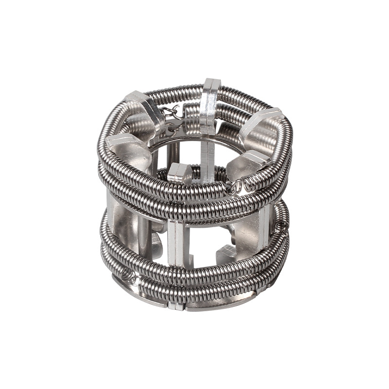 Current pathConductive ComponentsTulip contacts, flat contacts, fixed contacts, contact arms and supporting conductors.
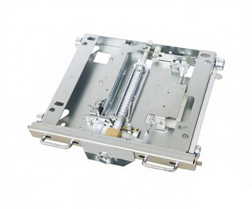 RackingChassis Trucks & Racking SystemsManual and motorized chassis trucks, racking mechanisms and control modules.
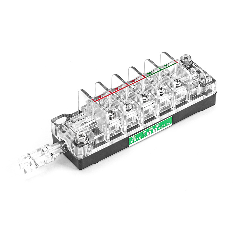 AuxiliaryAuxiliary & Magnetic Blowout SwitchesF-series auxiliary switches, LXW limit switches and CSK magnetic blowout switches.
Start with the breaker reference and component function. These five inputs separate current-path, chassis, secondary-connection and auxiliary-switching requirements before compatibility review.
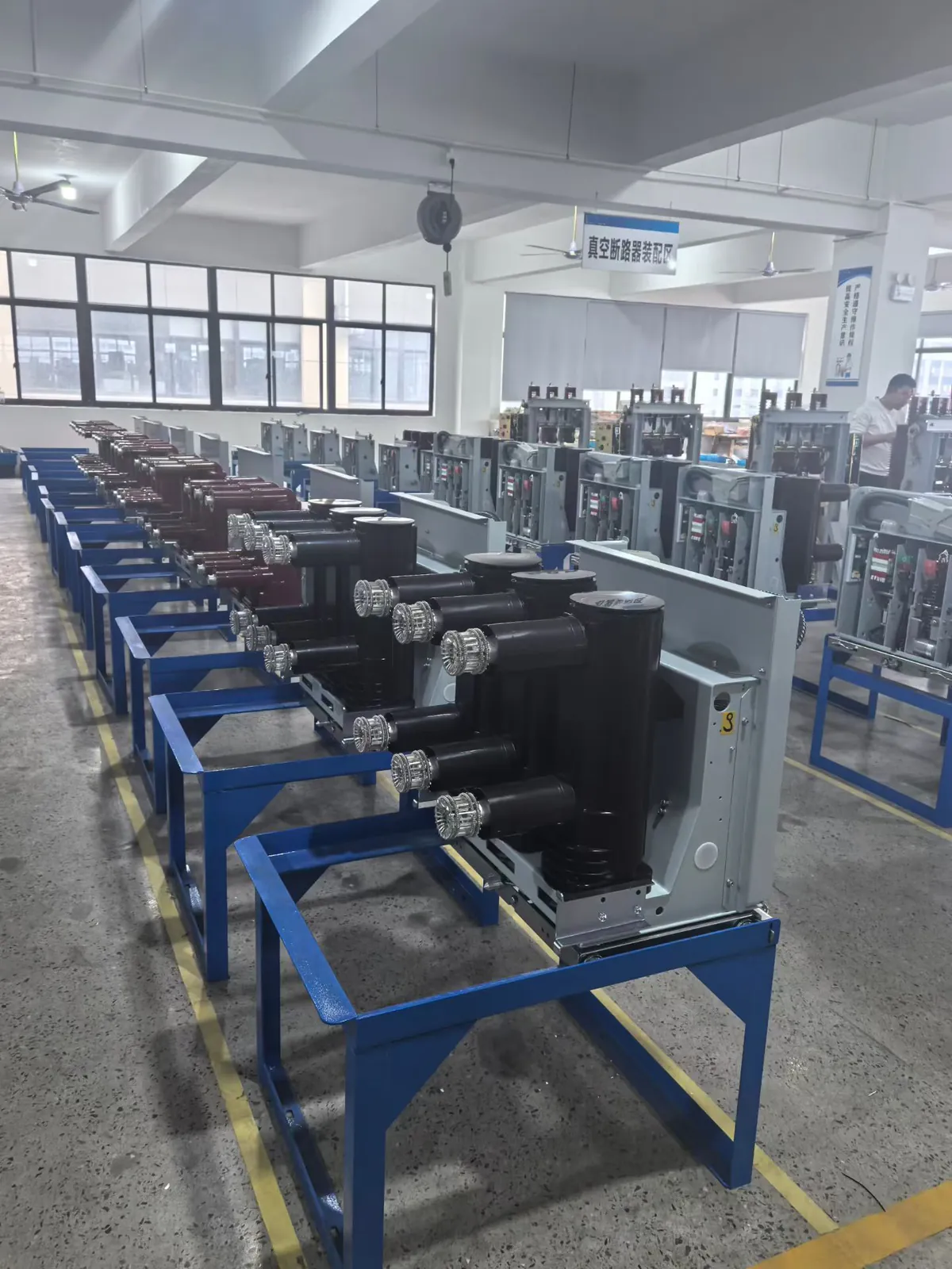
Choose the project situation first. Each route defines what to provide and what the engineering review can return.
Breaker fit, interface references and available production evidence are reviewed in one sequence before the component is specified for the project.
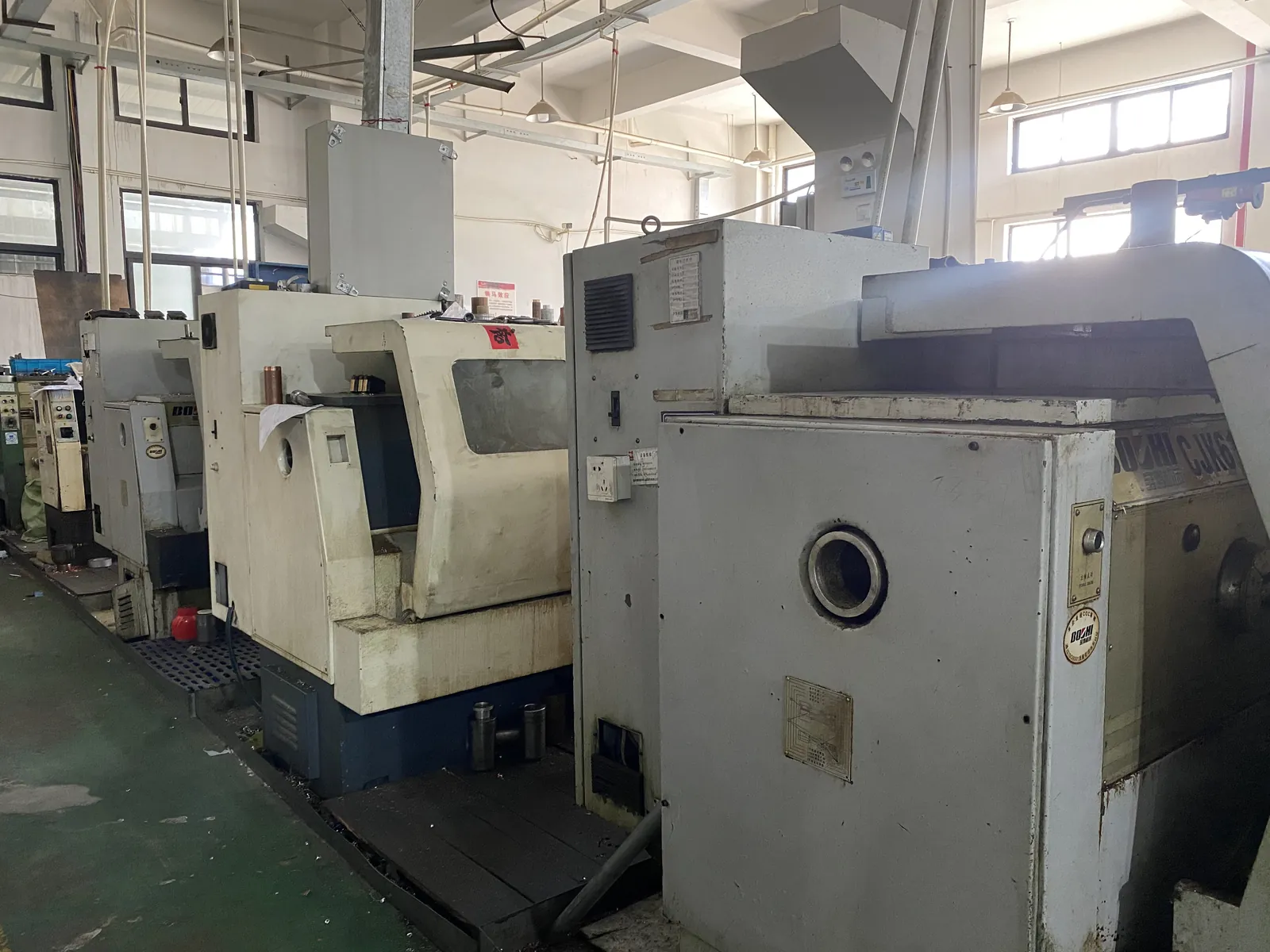
The breaker model, component function and available drawing or sample are reviewed before a part family is selected.
Breaker reference, component group and source record
Mating geometry, mounting pattern, travel, terminals or contact sequence are checked against the supplied reference.
Dimensions, interface notes and drawing revision
Applicable machining, assembly and inspection records are reviewed with the product identification before release.
Inspection status, product label and release record
Continue with practical background on vacuum circuit breakers, chassis interfaces and component selection.
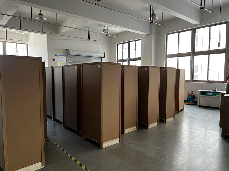
Understand the breaker function and operating context that define the interfaces of its conductive, mechanical and control components.
Review the chassis dimensions, travel and breaker interface that must be confirmed before replacement.
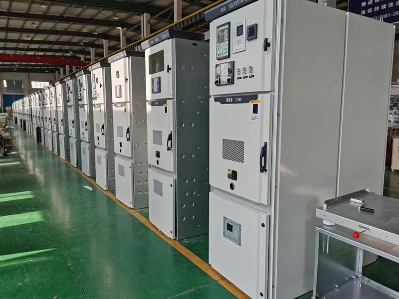
Use the cabinet and equipment context to organize a component request before model matching begins.
These answers clarify the current-path, racking, secondary-control and RFQ inputs that should be confirmed before a component is specified.
Start with the circuit-breaker model, component function and installed or proposed arrangement. For the relevant group, provide the primary or control duty, interface dimensions, existing part reference, drawings or photos, and the information needed to confirm the breaker, chassis or secondary-circuit connection.
No. Confirm the contact form, mating diameter or flat-contact geometry, insertion or connection arrangement, material or surface requirement where specified, pole position and the installed drawing as well as the electrical rating. A rating match alone does not confirm a usable interface.
Provide the breaker model, chassis width, mounting pattern, racking travel, drive position, wheel or rail arrangement, operating direction and the relevant interlock points. Use the installed drawing and measured dimensions to confirm the mechanical interface before ordering.
Confirm the plug or socket reference, pole count, keying or orientation, terminal assignment, control voltage, wiring diagram and installed clearance. A connector image alone does not confirm the mating arrangement or circuit function.
State the installed model, contact schedule, NO/NC logic, terminal assignment, shaft or actuator form, operating linkage, fixing pattern and required control duty. For a replacement, include the wiring diagram or terminal schedule and clear mechanism photos.
For a confirmed product family or model, request the applicable outline or mounting drawing and the relevant electrical, contact, terminal or interface data. Include the breaker reference, project requirement and document revision need so the review remains model-specific.