Specify epoxy-resin indoor current transformers (CTs) and voltage transformers (VTs) for medium-voltage switchgear. Compare 18 models for metering, protection, earth-fault detection and three-phase voltage measurement, then check ratio, accuracy class, burden, insulation level, secondary configuration and mounting dimensions before requesting a quote.
Indoor Current and Voltage Transformer Models and Specifications
Filter 10 indoor voltage transformer models and 8 indoor current transformer models. Select any card to compare model-specific ratios, accuracy classes, burdens, dimensions and overall drawings.
Technical data and dimensions
Indoor Current Transformer
LZZBJ9-10A1
Indoor current-transformer family with metering, protection and multi-core accuracy combinations across 5 A to 3150 A primary-current rows.
0.2 or 0.2S: 10 VA; 0.5 or 0.5S: 10 VA; 10P10: 15 VA; 10P15: 15 VA
Surface creepage distance
245 mm
Weight
21/23 kg
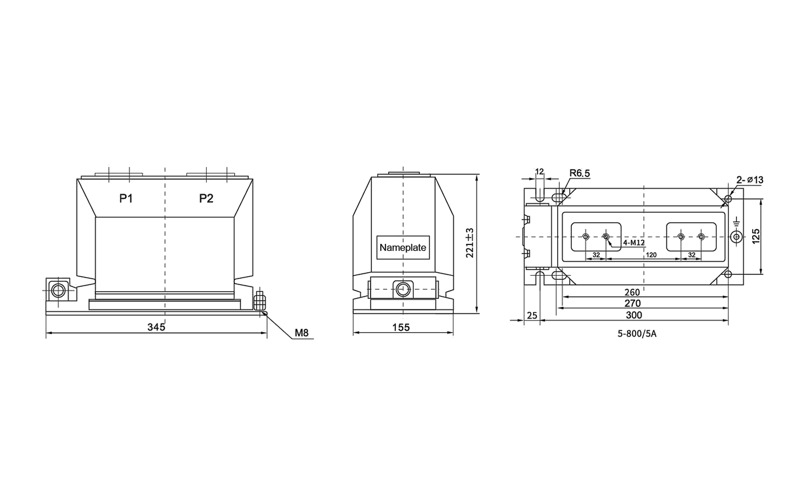
Key dimensions shown: Drawing values include 345 mm overall base length, 155 mm width, 221±3 mm height, 260/270/300 mm fixing references, 125 mm, 25 mm, 12 mm, R6.5, 2-Ø13, 4-M12, M8 and the shown 5-800/5A marking.
Technical specification tables
LZZBJ9-10A1 — Rated primary current and short-circuit current data
Rated primary current (A)
1 s thermal current (kA)
Rated dynamic current (kA)
5
0.75
1.8
10
1.5
3.75
15
2
5
20, 25
3
7.5
30
5
12.5
40
6.3
15.8
50, 60
8
20
75
12.5
31
100
15
37.5
150
30
75
200, 250
45
112.5
300
45
112.5
400
45
112.5
500
45
112.5
600
45
112.5
750, 800
63
130
1000
63
130
1200, 1250
80
160
1500
80
160
2000
80
160
2500
80
160
3000
80
160
3150
80
160
Overall dimension drawing
Check the overall dimensions, mounting centres, terminals and primary interface against the switchgear layout. Open the full-size view for closer inspection.
Before ordering, confirm the selected ratio, accuracy class, burden, secondary arrangement, insulation level and cabinet interface for this model.
LZZBJ9-10A1 overall dimension drawing
Technical data and dimensions
Indoor Current Transformer
LZZBJ9-10Q B6
Indoor current transformer with 5 A to 1000 A primary-current groups, metering/protection class combinations and grouped secondary outputs.
Standards
GB 20840.2-2014 and IEC 60044-1
Rated insulation level
12/42/75 kV
Rated secondary current
5 A or 1 A
Rated frequency
50 Hz or 60 Hz
Ambient temperature
-5 °C to +40 °C
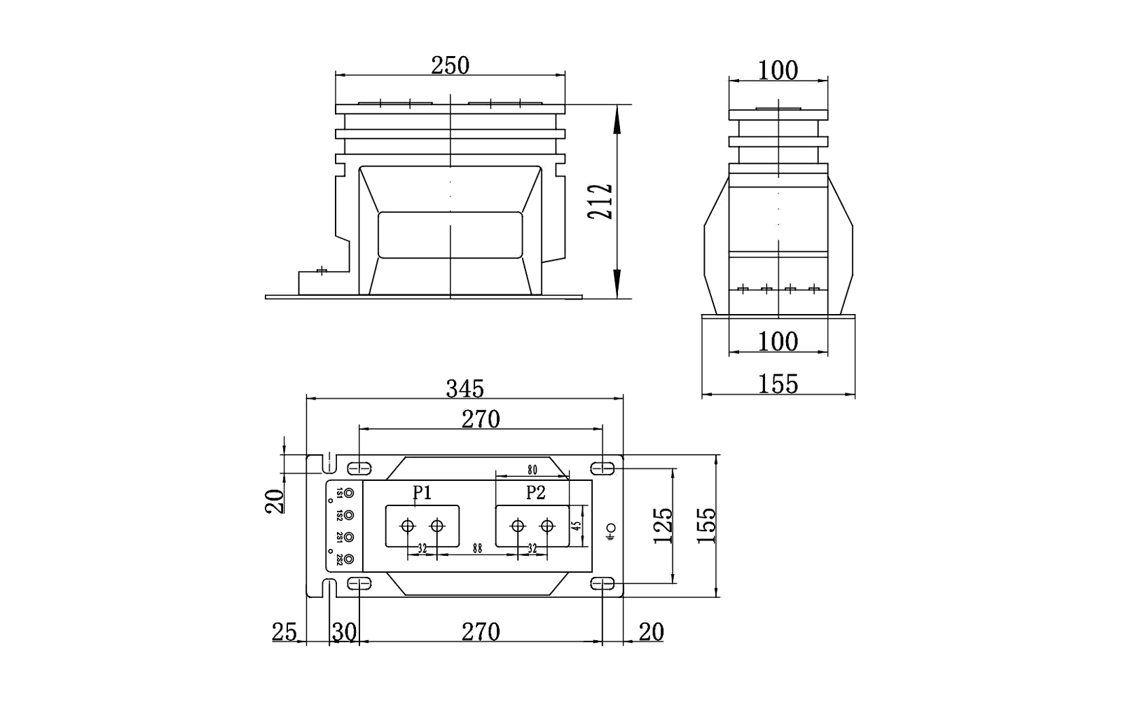
Key dimensions shown: Drawing values include 250 mm and 100 mm top references, 212 mm height, 345 mm overall length, 270 mm fixing span, 155/156 mm width references, 125 mm, 80 mm, 30 mm, 25 mm and 20 mm.
Technical specification tables
LZZBJ9-10Q B6 — Accuracy, burden and short-circuit data
Rated primary current (A)
Accuracy classes combination
0.2/0.5S output (VA)
0.2/0.5 output (VA)
10P15 output (VA)
1 s thermal current (kA)
Rated dynamic current (kA)
5-100
—
—
—
—
150 × Iin
375 × Iin
150
0.2S/10P15
10
—
15
22.5
45
200
0.5S/10P15
10
—
15
24.5
50
300, 400
0.2/10P15
—
10
15
45
90
500, 600
0.5/10P15
—
15
20
45
90
800-1000
0.5/10P15
—
15
20
63
110
Overall dimension drawing
Check the overall dimensions, mounting centres, terminals and primary interface against the switchgear layout. Open the full-size view for closer inspection.
Before ordering, confirm the selected ratio, accuracy class, burden, secondary arrangement, insulation level and cabinet interface for this model.
LZZBJ9-10Q B6 overall dimension drawing
Technical data and dimensions
Indoor Current Transformer
LMZK-10
Ring-type CT family covering LMZK-10C measuring, LMZK-10P protective and LMZK-10CP combined-winding configurations.
LMZK-10C
Measuring current transformer; classes 0.2, 0.5 and 3
LMZK-10P
Protective current transformer; classes 10P15, 10P10 and 10P5
LMZK-10CP
Combined-winding current transformer; classes 0.5, 1, 10P10 and 10P5
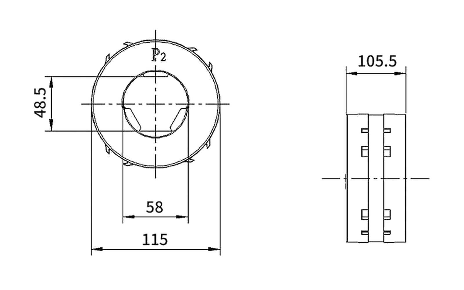
Key dimensions shown: Drawing values include 115 mm outside width, 58 mm opening reference, 48.5 mm centre reference and 105.5 mm body depth.
Technical specification tables
LMZK-10 — Accuracy class and rated load (VA)
Current ratio I1/I2
C 0.2
C 0.5
C 3
P 10P15
P 10P10
P 10P5
CP 0.5
CP 1
CP 10P10
CP 10P5
20/1
—
—
0.5
—
—
0.75
—
—
—
—
30/1
—
—
1.5
—
0.75
1.25
—
—
—
—
40/1
—
—
2
—
1
1.5
—
—
—
—
50/1
—
—
2
—
1.25
2
—
—
—
1.25
75/1
—
2
3.75
1.25
2
3
—
2
1
2
100/1
—
2.5
5
2
2.5
—
2
2.5
1.5
2.5
150/1
—
3.75
5
2.5
3.75
—
2.5
—
2
—
200/1
—
5
7.5
3
5
7.5
2.5
—
2.5
—
300/1
—
10
15
3
5
7.5
3.75
—
2.5
—
400/1
2.5
10
—
3
5
10
5
—
2.5
—
500/1
5
25
—
3.75
6.25
10
5
—
2.5
—
600/1
5
25
—
5
7.5
10
7.5
—
3.75
—
50/5
—
—
2.5
—
—
2
—
—
—
—
75/5
—
—
2.5
—
—
3
—
2
—
1.5
100/5
—
2.5
3.75
—
2.5
5
—
—
—
2
150/5
—
5
7.5
—
3
5
2.5
—
1.25
2
200/5
—
7.5
—
—
3.75
—
2.5
—
1.5
2.5
300/5
—
10
—
—
3.75
—
2.5
—
2
2.5
400/5
5
15
—
—
5
—
7.5
—
2
5
500/5
7.5
25
—
—
5
—
7.5
—
2
6.25
600/5
10
30
—
—
7.5
—
10
—
3
7.5
Overall dimension drawing
Check the overall dimensions, mounting centres, terminals and primary interface against the switchgear layout. Open the full-size view for closer inspection.
LMZK-10 model-specific overall dimension drawing
Before ordering, confirm the selected ratio, accuracy class, burden, secondary arrangement, insulation level and cabinet interface for this model.
LMZK-10 overall dimension drawing
Technical data and dimensions
Indoor Current Transformer
LMZC-10
Ring-type current transformer with measuring, protection and double-winding burden options across two grouped ratio tables.
Measuring classes
0.2S, 0.2 and 0.5
Protection classes
10P5, 10P10 and 10P15
Double-winding classes
0.5, 1, 10P5 and 10P10
Ratio confirmation
The two table blocks list ratio values without a printed secondary-current suffix. Include the complete required primary/secondary ratio in the RFQ.
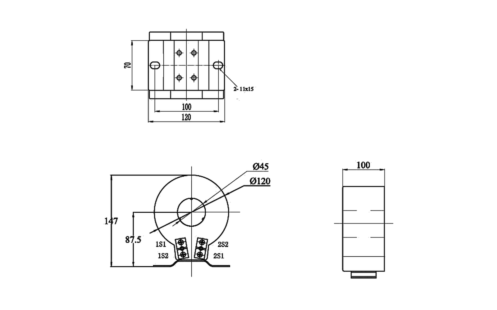
Key dimensions shown: Drawing values include Ø120 and Ø45 openings, 120/100 mm references, 87.5 mm terminal reference and 2-11×15 mounting slots.
Technical specification tables
LMZC-10 — Accuracy class and rated burden (VA)
Ratio group
Ratio
M 0.2S
M 0.2
M 0.5
P 10P5
P 10P10
P 10P15
DW 0.5
DW 1
DW 10P5
DW 10P10
A
75
—
—
—
—
—
—
—
—
—
—
A
100
—
—
—
2.5
—
—
—
—
—
—
A
150
2.5
2.5
2.5
2.5
—
—
—
—
—
—
A
200
2.5
2.5
2.5
3.75
—
—
—
—
—
—
A
300
5
5
5
5
—
—
—
—
—
—
A
400
5
5
5
5
2.5
—
—
—
—
—
A
500
10
10
10
7.5
2.5
—
—
—
—
—
A
600
10
10
10
10
5
—
—
—
—
—
B
50
—
—
2.5
—
—
—
—
—
—
—
B
75
2.5
3.75
3.75
2.5
—
—
—
—
—
—
B
100
5
5
5
5
2.5
1.5
—
—
—
—
B
150
5
5
5
7.5
3.75
1.5
—
—
—
—
B
200
7.5
7.5
7.5
10
5
2.5
5
5
2.5
—
B
300
10
10
15
20
7.5
5
7.5
7.5
3.75
—
B
400
15
20
20
20
10
7.5
7.5
7.5
5
2.5
B
500
15
20
20
20
10
7.5
20
10
5
2.5
B
600
15
20
20
—
10
7.5
20
10
7.5
3.75
Overall dimension drawing
Check the overall dimensions, mounting centres, terminals and primary interface against the switchgear layout. Open the full-size view for closer inspection.
LMZC-10 model-specific overall dimension drawing
Before ordering, confirm the selected ratio, accuracy class, burden, secondary arrangement, insulation level and cabinet interface for this model.
LMZC-10 overall dimension drawing
Technical data and dimensions
Indoor Current Transformer
LSY-107-75-65
Three-phase current-transformer assembly with measuring, protective and double-winding burden selections from ratio 75 through 800.
Measuring classes
0.2S, 0.2 and 0.5
Protection classes
10P10, 10P15 and 10P20
Double-winding classes
0.2S, 0.5, 10P10 and 10P15
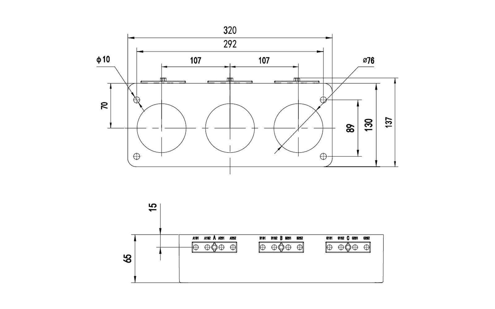
Key dimensions shown: Drawing values include 320 mm overall length, 292 mm fixing reference, two 107 mm phase spacings, Ø78 openings, Ø10 fixing holes, 96/168/173 mm height references and a 66 mm terminal section with 15 mm offset.
Technical specification tables
LSY-107-75-65 — Accuracy class and rated burden (VA)
Ratio
M 0.2S
M 0.2
M 0.5
P 10P10
P 10P15
P 10P20
DW 0.2S
DW 0.5
DW 10P10
DW 10P15
75
—
—
1
—
—
—
—
1
—
—
100
—
—
2.5
—
—
—
—
1
—
—
150
—
—
2.5
2.5
—
—
—
1.5
—
—
200
—
2.5
2.5
5
—
—
—
2.5
5
—
300
2.5
2.5
5
5
—
—
—
2.5
5
—
400
5
5
5
7.5
—
—
—
5
7.5
—
500
5
5
10
10
—
—
—
5
10
—
600
5
10
10
10
—
—
—
5
10
—
800
10
10
10
10
—
—
—
5
10
—
Overall dimension drawing
Check the overall dimensions, mounting centres, terminals and primary interface against the switchgear layout. Open the full-size view for closer inspection.
Before ordering, confirm the selected ratio, accuracy class, burden, secondary arrangement, insulation level and cabinet interface for this model.
LSY-107-75-65 overall dimension drawing
Technical data and dimensions
Indoor Current Transformer
LXK-80-240
Zero-sequence current transformer with relay-winding connection data for DD-11/60 and DD-1/60 relays.
Duty
Zero-sequence current-transformer and relay connection reference
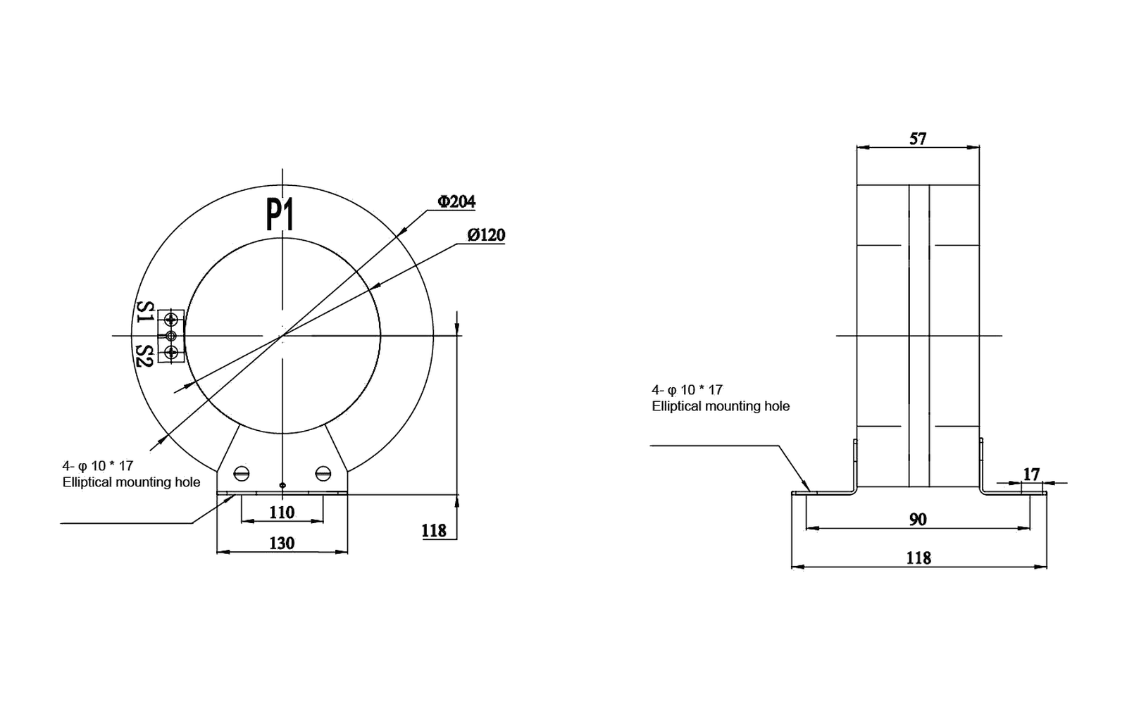
Key dimensions shown: Drawing values include Ø204 outside diameter, Ø120 opening, 130 mm, 118 mm, 110 mm, 90 mm, 57 mm and 4-10×17 elliptical mounting holes.
Technical specification tables
LXK-80-240 — Relay connection and primary zero-sequence current
Type of relay
Relay winding connection
Relay setting current (mA)
Primary zero-sequence current (A)
DD-11/60
Series
15×1; 30×1
2.4-4.5
DD-11/60
Parallel
15×2; 30×2
3-5
DD-1/60
Series
15×1; 30×1
3-5
DD-1/60
Parallel
15×2; 30×2
3-6
Overall dimension drawing
Check the overall dimensions, mounting centres, terminals and primary interface against the switchgear layout. Open the full-size view for closer inspection.
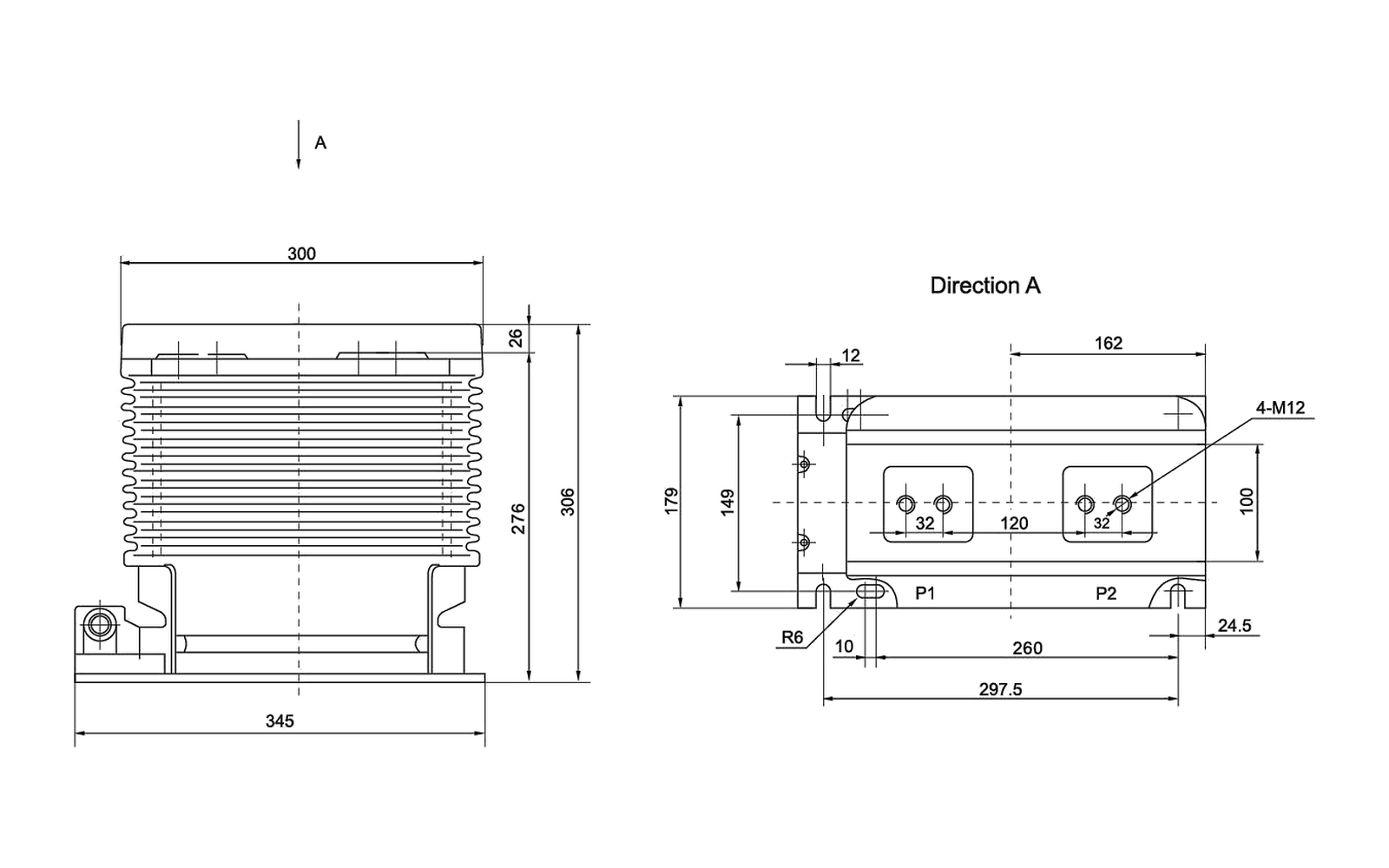
Key dimensions shown: Drawing values include 345 mm base length, 300 mm, 306/276 mm, 297.5/260 mm, 149/129/120 mm, 162 mm, 32 mm, 24.5 mm, 12 mm, 10 mm, R6, 4-M12 and P1/P2 terminal markings.
Technical specification tables
LZZB9-24/180b/2 — Primary current, output and short-circuit data
Rated primary current (A)
0.2(S) output (VA)
0.5(S) output (VA)
10P10 output (VA)
10P15 output (VA)
1 s thermal current (kA)
Rated dynamic current (kA)
20-150
10
10
15
10
150 × Iin
375 × Iin
200
10
10
15
10
31.5
80
300-500
10
10
15
10
45
112.5
600, 800
15
20
20
15
63
130
1000, 1200
15
20
20
15
80
160
Overall dimension drawing
Check the overall dimensions, mounting centres, terminals and primary interface against the switchgear layout. Open the full-size view for closer inspection.
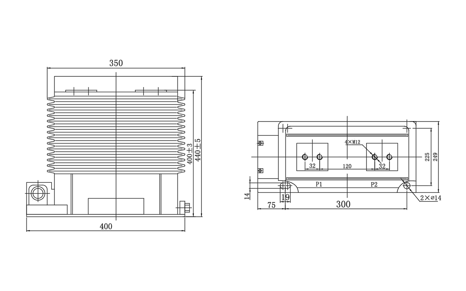
Key dimensions shown: Drawing values include 400 mm base length, 350 mm top reference, 300 mm fixing span, 120 mm, 32 mm, 4-M12 and 2-Ø14 mounting references.
Technical specification tables
LZZBJ9-35/250W1G1 — Primary current, output and short-circuit data
Rated primary current (A)
0.2 output (VA)
0.5 output (VA)
10P20 output (VA)
Short-time thermal current (kA/s)
Rated dynamic current (kA)
20-100
10
15
15
200 × Iin
500 × Iin
150-200
10
15
15
31.5
80
300-500
10
15
15
31.5/2
80
600-1250
15
30
20
31.5/4
80
1500-2000
20
40
30
40/4
125
2500
20
40
20
40/4
125
Overall dimension drawing
Check the overall dimensions, mounting centres, terminals and primary interface against the switchgear layout. Open the full-size view for closer inspection.
Before ordering, confirm the selected ratio, accuracy class, burden, secondary arrangement, insulation level and cabinet interface for this model.
LZZBJ9-35/250W1G1 overall dimension drawing
Technical data and dimensions
Indoor Voltage Transformer
JDZ(J)-10Q
JDZ and JDZJ indoor voltage-transformer family with phase-to-phase and phase-to-earth ratio rows, multiple accuracy burdens and 6P options.
Standards
GB 20840.3-2013 and IEC 60044-2
Rated insulation levels
12/42/75 kV and 7.2/32/60 kV; row-specific 3.6/25/40 kV values are also listed
Rated frequency
50 Hz or 60 Hz
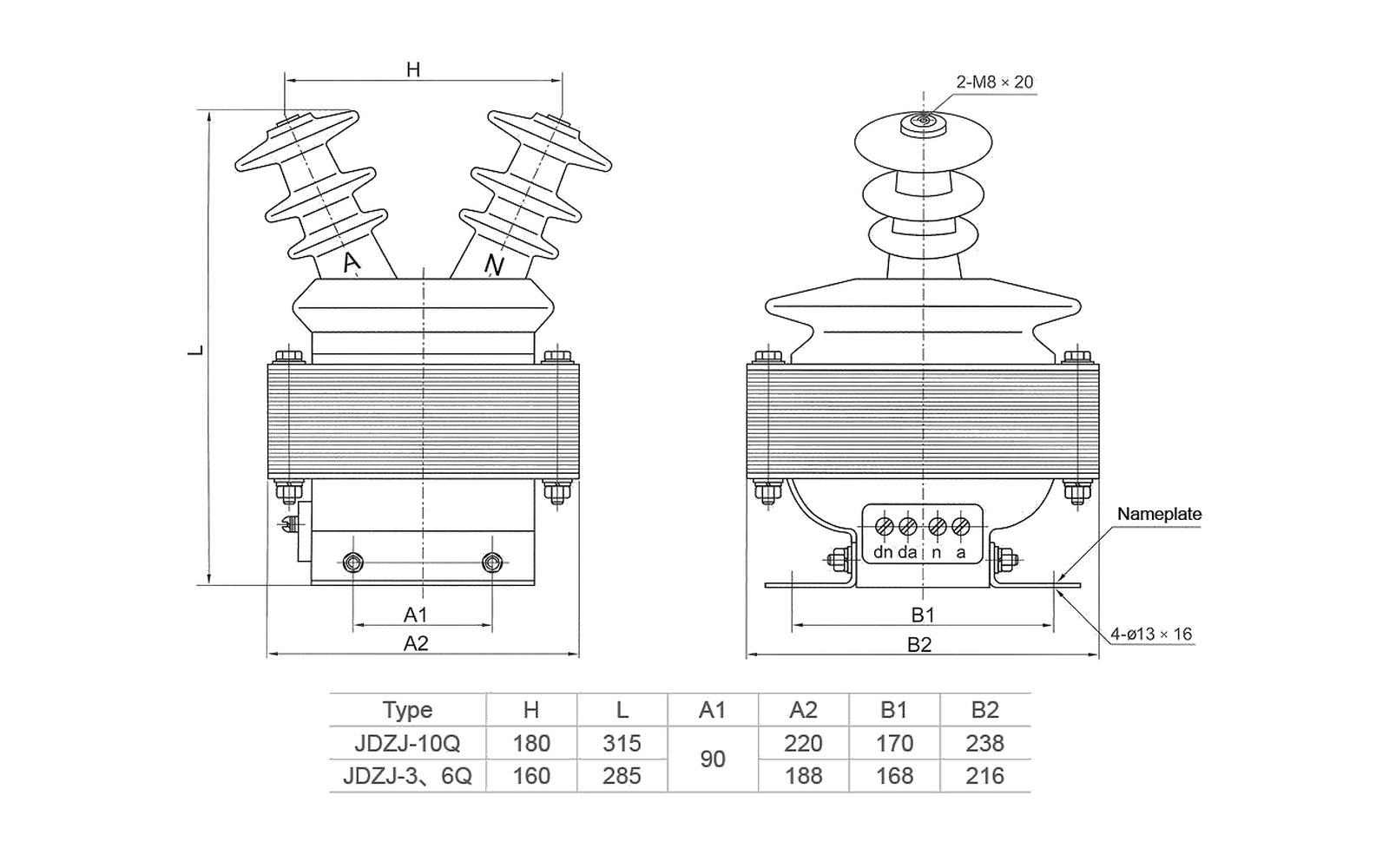
Key dimensions shown: Drawing type table: JDZJ-10Q H 180, L 315, A1 90, A2 220, B1 170, B2 238 mm; JDZJ-3/6Q H 160, L 285, A1 50, A2 188, B1 168, B2 216 mm. The drawing also identifies A/N terminals and 2-M8.
Technical specification tables
JDZ(J)-10Q — Rated voltage ratio and secondary output
Type
Rated voltage ratio (V)
0.2 (VA)
0.5 (VA)
Class 1 (VA)
Class 3 (VA)
0.2/0.2 or 0.2/0.5 (VA)
0.5/0.5 (VA)
6P (VA)
Max output (VA)
Rated insulation level (kV)
JDZ-3Q
3000/100
20
30
50
80
15/15
30/30
/
200
3.6/25/40
JDZ-6Q
6000/100
30
50
80
200
15/15
30/30
/
400
7.2/32/60
JDZ-10Q
10000/100
30
80
150
300
15/20
50/50
/
500
12/42/75
JDZJ-3Q
3000/√3 / 100/√3 / 100/3
20
30
50
80
/
/
50
200
3.6/25/40
JDZJ-6Q
6000/√3 / 100/√3 / 100/3
20
50
80
200
/
/
50
400
7.2/32/60
JDZJ-10Q
10000/√3 / 100/√3 / 100/3
20
50
80
200
/
/
100
400
12/42/75
JDZJ-10Q
10000/√3 / 100/√3 / 100/√3 / 100/3
/
/
/
/
15/15
25/25
100
200/200
12/42/75
Overall dimension drawing
Check the overall dimensions, mounting centres, terminals and primary interface against the switchgear layout. Open the full-size view for closer inspection.
Before ordering, confirm the selected ratio, accuracy class, burden, secondary arrangement, insulation level and cabinet interface for this model.
JDZ(J)-10Q overall dimension drawing
Technical data and dimensions
Indoor Voltage Transformer
JDZ10-10
Indoor voltage transformer with 3000/100, 6000/100 and 10000/100 ratio rows and class 0.2 through class 3 burden data.
Standards
GB 20840.3-2013 and IEC 60044-2
Rated insulation levels
3.6/25/40, 7.2/32/60 and 12/42/75 kV by ratio row
Rated frequency
50 Hz or 60 Hz
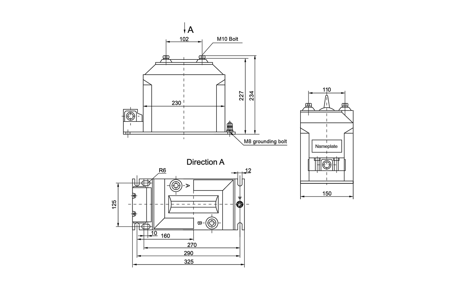
Key dimensions shown: Drawing values include 325/290/270 mm base references, 230 mm body width, 234 mm and 102/110 mm height references, 160/150/10 mm, R6, M10 primary bolt and M8 grounding bolt.
Technical specification tables
JDZ10-10 — Rated voltage ratio and secondary output
Rated voltage ratio (V)
0.2 (VA)
0.5 (VA)
Class 1 (VA)
Class 3 (VA)
Max output (VA)
Rated insulation level (kV)
3000/100
15
30
60
150
200
3.6/25/40
6000/100
15
30
60
150
200
7.2/32/60
10000/100
15
30
60
150
200
12/42/75
Overall dimension drawing
Check the overall dimensions, mounting centres, terminals and primary interface against the switchgear layout. Open the full-size view for closer inspection.
JDZ10-10 model-specific overall dimension drawing
Before ordering, confirm the selected ratio, accuracy class, burden, secondary arrangement, insulation level and cabinet interface for this model.
JDZ10-10 overall dimension drawing
Technical data and dimensions
Indoor Voltage Transformer
JDZX10-10
Phase-to-earth indoor voltage transformer with three ratio rows, class 0.2 through class 3 outputs and a 6P burden.
Standards
GB 20840.3-2013 and IEC 60044-2
Rated insulation levels
3.6/25/40, 7.2/32/60 and 12/42/75 kV by ratio row
Rated frequency
50 Hz or 60 Hz
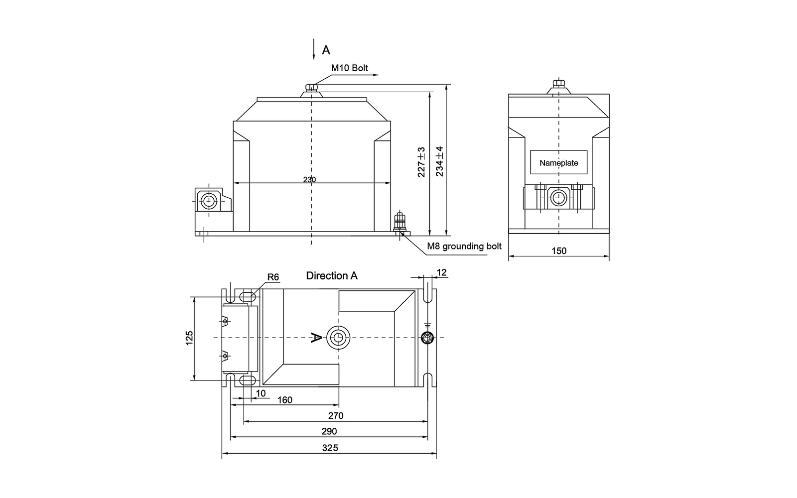
Key dimensions shown: Drawing values include 325/290/270 mm base references, 227±3 and 234±4 mm heights, 160/150/10 mm, R6, M10 primary bolt and M8 grounding bolt.
Technical specification tables
JDZX10-10 — Rated voltage ratio and secondary output
Rated voltage ratio (V)
0.2 (VA)
0.5 (VA)
Class 1 (VA)
Class 3 (VA)
6P (VA)
Max output (VA)
Rated insulation level (kV)
3000/√3 / 100/√3 / 100/3
15
30
60
150
50
200
3.6/25/40
6000/√3 / 100/√3 / 100/3
15
30
60
150
50
200
7.2/32/60
10000/√3 / 100/√3 / 100/3
15
30
60
150
50
200
12/42/75
Overall dimension drawing
Check the overall dimensions, mounting centres, terminals and primary interface against the switchgear layout. Open the full-size view for closer inspection.
Before ordering, confirm the selected ratio, accuracy class, burden, secondary arrangement, insulation level and cabinet interface for this model.
JDZX10-10 overall dimension drawing
Technical data and dimensions
Indoor Voltage Transformer
JDZX9-10Q
Indoor voltage transformer with three- and four-winding ratio rows, multiple measurement outputs and 6P burden data.
Standards
GB 20840.3-2013 and IEC 60044-2
Rated insulation levels
3.6/25/40, 7.2/32/60 and 12/42/75 kV by ratio row
Rated frequency
50 Hz or 60 Hz
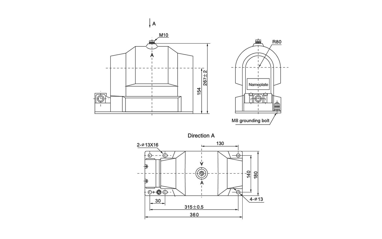
Key dimensions shown: Drawing values include 360 mm overall base, 315±0.5 mm fixing span, 267±2 mm height, 154/130/30 mm, R80, 2-Ø13×16, 4-Ø13, M10 primary and M8 grounding hardware.
Technical specification tables
JDZX9-10Q — Rated voltage ratio and secondary output
Rated voltage ratio (V)
0.2 (VA)
0.5 (VA)
Class 1 (VA)
Class 3 (VA)
0.2/0.2 or 0.2/0.5 (VA)
0.5/0.5 (VA)
6P (VA)
Max output (VA)
Rated insulation level (kV)
3000/√3 / 100/√3 / 100/3
30
80
180
500
/
/
100
600
3.6/25/40
6000/√3 / 100/√3 / 100/3
30
80
180
500
/
/
100
600
7.2/32/60
10000/√3 / 100/√3 / 100/3
30
80
180
500
/
/
100
600
12/42/75
10000/√3 / 100/√3 / 100/√3 / 100/3
/
/
/
/
15/15 or 15/20
45/45
100
300/300
12/42/75
Overall dimension drawing
Check the overall dimensions, mounting centres, terminals and primary interface against the switchgear layout. Open the full-size view for closer inspection.
Before ordering, confirm the selected ratio, accuracy class, burden, secondary arrangement, insulation level and cabinet interface for this model.
JDZX9-10Q overall dimension drawing
Technical data and dimensions
Indoor Voltage Transformer
JDZ8-10R
Indoor voltage transformer with 3000 V through 10000 V primary-ratio rows plus dual-secondary configurations.
Standards
GB 20840.3-2013 and IEC 60044-2
Rated insulation levels
3.6/23/40, 7.2/32/60 and 12/42/75 kV by ratio row
Rated frequency
50 Hz or 60 Hz
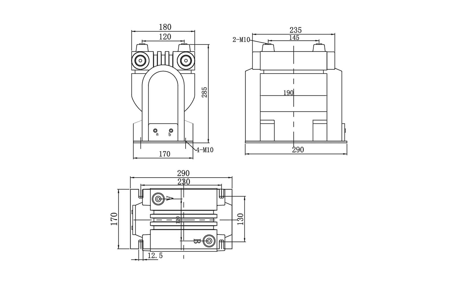
Key dimensions shown: Drawing values include 290/285/235/230/190/180/170/145/120 mm references, 2-M10 and 4-M10 mounting or terminal hardware.
Technical specification tables
JDZ8-10R — Rated voltage ratio and secondary output
Rated voltage ratio (V)
0.2 (VA)
0.5 (VA)
Class 1 (VA)
Class 3 (VA)
0.2/0.2 or 0.2/0.5 (VA)
0.5/0.5 (VA)
Max output (VA)
Rated insulation level (kV)
3000/100
30
80
150
250
/
/
600
3.6/23/40
6000/100
30
80
150
250
/
/
600
7.2/32/60
10000/100
30
80
150
250
/
/
600
12/42/75
10000/220
30
80
150
250
/
/
600
12/42/75
10000/100/100
/
/
/
/
15/15 or 15/20
40/40
300/300
12/42/75
10000/100/220
/
/
/
/
0.2/3—30/250; 0.5/3—80/250
—
300/500
12/42/75
Overall dimension drawing
Check the overall dimensions, mounting centres, terminals and primary interface against the switchgear layout. Open the full-size view for closer inspection.
JDZ8-10R model-specific overall dimension drawing
Before ordering, confirm the selected ratio, accuracy class, burden, secondary arrangement, insulation level and cabinet interface for this model.
JDZ8-10R overall dimension drawing
Technical data and dimensions
Indoor Voltage Transformer
JDZX18-10R1
Phase-to-earth indoor voltage transformer with three- and four-winding ratio configurations and a 6P burden.
Standards
GB 20840.3-2013 and IEC 60044-2
Rated insulation levels
3.6/25/40, 7.2/32/60 and 12/42/75 kV by ratio row
Rated frequency
50 Hz or 60 Hz
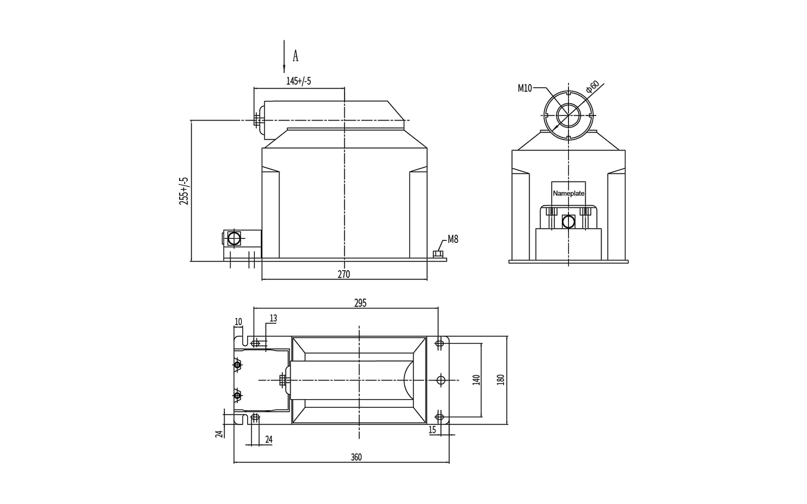
Key dimensions shown: Drawing values include 360/295/270 mm base references, 255±5 mm body height, 145±5 mm width reference, 24/13 mm and M10/M8 hardware.
Technical specification tables
JDZX18-10R1 — Rated voltage ratio and secondary output
Rated voltage ratio (V)
0.2 (VA)
0.5 (VA)
Class 1 (VA)
Class 3 (VA)
0.2/0.2 or 0.2/0.5 (VA)
0.5/0.5 (VA)
6P (VA)
Max output (VA)
Rated insulation level (kV)
3000/√3 / 100/√3 / 100/3
25
50
90
200
/
/
50
400
3.6/25/40
6000/√3 / 100/√3 / 100/3
25
50
90
200
/
/
50
400
7.2/32/60
10000/√3 / 100/√3 / 100/3
25
50
90
200
/
/
50
400
12/42/75
10000/√3 / 100/√3 / 100/√3 / 100/3
/
/
/
/
15/15 or 15/20
30/30
50
200/200
12/42/75
Overall dimension drawing
Check the overall dimensions, mounting centres, terminals and primary interface against the switchgear layout. Open the full-size view for closer inspection.
Before ordering, confirm the selected ratio, accuracy class, burden, secondary arrangement, insulation level and cabinet interface for this model.
JDZX18-10R1 overall dimension drawing
Technical data and dimensions
Indoor Voltage Transformer
JDZX10-10R / JDZ16-10R
Family table covering JDZ12A and JDZ16 standard and R variants with single- and dual-secondary ratios.
Standards
GB 20840.3-2013 and IEC 60044-2
Rated insulation levels
3.6/23/40, 7.2/32/60 and 12/42/75 kV by type and ratio row
Rated frequency
50 Hz or 60 Hz
Primary connection option
For JDZ12A-3, JDZ12A-6 and JDZ12A-10, the first connection point is designed for a 200 A American-style elbow connector. Confirm connector compatibility before ordering.
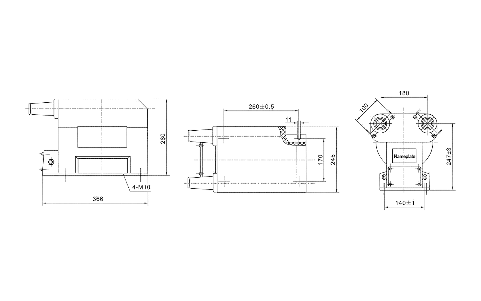
Key dimensions shown: Drawing values include 366/280/260±0.5/180/140±1 mm, 247±3 mm body height, 11 mm, 4-M10 and the nameplate location.
Technical specification tables
JDZX10-10R / JDZ16-10R — Standard variants
Type
Rated voltage ratio (V)
0.2 (VA)
0.5 (VA)
Class 1 (VA)
Class 3 (VA)
Combined accuracy/output
0.5/0.5 (VA)
Max output (VA)
Rated insulation level (kV)
JDZ12A-3
3000/100
30
90
250
400
/
/
1000
3.6/23/40
JDZ12A-6
6000/100
30
90
250
400
/
/
1000
7.2/32/60
JDZ16-6
10000/100
30
90
250
400
/
/
1000
12/42/75
JDZ16-6
10000/220
30
90
250
400
/
/
1000
12/42/75
JDZ12A-10 / JDZ16-10
10000/100/100
/
/
/
/
20/20 or 20/30
50/50
500/500
12/42/75
JDZ12A-10 / JDZ16-10
10000/100/200
/
/
/
/
0.2/3—30/400; 0.5/3—90/400
—
800/1000
12/42/75
JDZX10-10R / JDZ16-10R — R variants
Type
Rated voltage ratio (V)
0.2 (VA)
0.5 (VA)
Class 1 (VA)
Class 3 (VA)
Combined accuracy/output
0.5/0.5 (VA)
Max output (VA)
Rated insulation level (kV)
JDZ12A-3R
3000/100
30
90
250
400
/
/
1000
3.6/23/40
JDZ12A-6R
6000/100
30
90
250
400
/
/
1000
7.2/32/60
JDZ16-6R
10000/100
30
90
250
400
/
/
1000
12/42/75
JDZ16-6R
10000/200
30
90
250
400
/
/
1000
12/42/75
JDZ12A-10R / JDZ16-10R
10000/100/100
/
/
/
/
20/20 or 20/30
50/50
500/500
12/42/75
JDZ12A-10R / JDZ16-10R
10000/100/220
/
/
/
/
0.2/3—30/400; 0.5/3—90/400
—
800/1000
12/42/75
Overall dimension drawing
Check the overall dimensions, mounting centres, terminals and primary interface against the switchgear layout. Open the full-size view for closer inspection.
Before ordering, confirm the selected ratio, accuracy class, burden, secondary arrangement, insulation level and cabinet interface for this model.
JDZX10-10R / JDZ16-10R overall dimension drawing
Technical data and dimensions
Indoor Voltage Transformer
JSZVR-10W
Three-phase indoor voltage transformer with single- and dual-secondary ratios and class 0.2 through class 1 output data.
Standards
GB 20840.3-2013 and IEC 60044-2
Rated insulation levels
3.6/23/40, 7.2/32/60 and 12/42/75 kV by ratio row
Rated frequency
50 Hz or 60 Hz
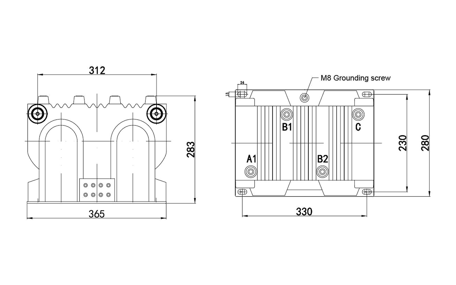
Key dimensions shown: Drawing values include 365/330/312 mm overall references, 283/280/230 mm heights and an M8 grounding screw; terminals are marked A1, B1, B2 and C.
Technical specification tables
JSZVR-10W — Rated voltage ratio and secondary output
Rated voltage ratio (V)
0.2 (VA)
0.5 (VA)
Class 1 (VA)
Class 3 (VA)
0.2/0.2 or 0.2/0.5 (VA)
0.5/0.5 (VA)
6P
Max output (VA)
Rated insulation level (kV)
3000/100
30
80
150
/
/
/
/
800
3.6/23/40
6000/100
30
80
150
/
/
/
/
800
7.2/32/60
10000/100
30
80
150
/
/
/
/
800
12/42/75
3000/100/100
/
/
/
/
20/20
40/40
/
400/400
3.6/23/40
6000/100/100
/
/
/
/
20/20
40/40
/
400/400
7.2/32/60
10000/100/100
/
/
/
/
20/20
40/40
/
400/400
12/42/75
10000/100/220
/
/
/
/
0.2/3—30/200; 0.5/3—80/200
—
/
600/800
12/42/75
Overall dimension drawing
Check the overall dimensions, mounting centres, terminals and primary interface against the switchgear layout. Open the full-size view for closer inspection.
Before ordering, confirm the selected ratio, accuracy class, burden, secondary arrangement, insulation level and cabinet interface for this model.
JSZVR-10W overall dimension drawing
Technical data and dimensions
Indoor Voltage Transformer
JSZV12A-10R
Three-phase indoor voltage transformer with star-connected secondary-output values expressed per √3 and a dual-secondary option.
Standards
GB 20840.3-2013 and IEC 60044-2
Rated insulation levels
3.6/23/40, 7.2/32/60 and 12/42/75 kV by ratio row
Rated frequency
50 Hz or 60 Hz
Primary connection option
For JSZV12A-3, JSZV12A-6 and JSZV12A-10R, the first connection point is designed for a 200 A American-style heavy-duty elbow connector. Confirm connector compatibility before ordering.
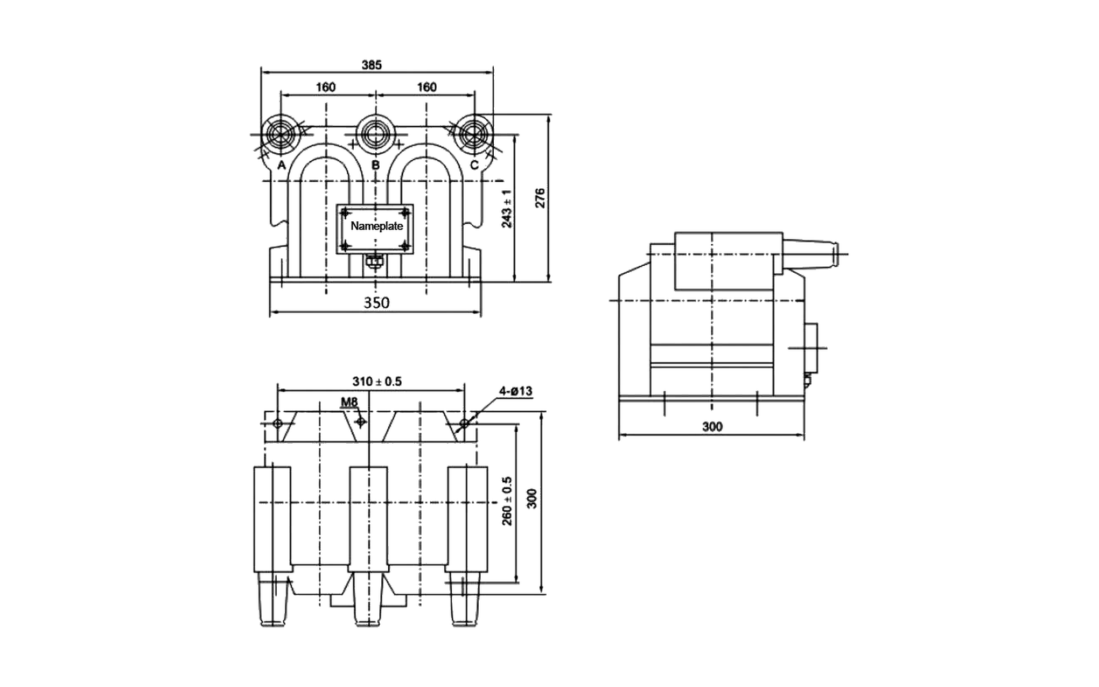
Key dimensions shown: Drawing values include 385 mm overall top width, two 160 mm phase spacings, 350 mm base, 310±0.5 mm fixing span, 300 mm depth/height references, 276 mm, 260±0.5 mm, 243±1 mm, M8 and 4-Ø13.
Technical specification tables
JSZV12A-10R — Three-phase rated secondary output
Rated voltage ratio (V)
Accuracy class and three-phase rated secondary output (VA)
Check the overall dimensions, mounting centres, terminals and primary interface against the switchgear layout. Open the full-size view for closer inspection.
Before ordering, confirm the selected ratio, accuracy class, burden, secondary arrangement, insulation level and cabinet interface for this model.
JSZV12A-10R overall dimension drawing
Technical data and dimensions
Indoor Voltage Transformer
JDZX9-35
35 kV nominal class phase-to-earth voltage transformer with measurement, residual-voltage and dual-secondary winding outputs.
Standards
GB 20840.3-2013 and IEC 60044-2
Rated insulation level
40.5/95/185 kV in the technical notes; the specification table lists 40.5/95/200 kV
Pollution class
Class II
Rated frequency
50 Hz or 60 Hz
Load power factor
cos φ = 0.8 lagging
Connection
For the 1/1/1-12-12 group, three single-phase voltage transformers form a Y0/Y0/open-delta group; the residual-voltage winding is connected in open triangle.
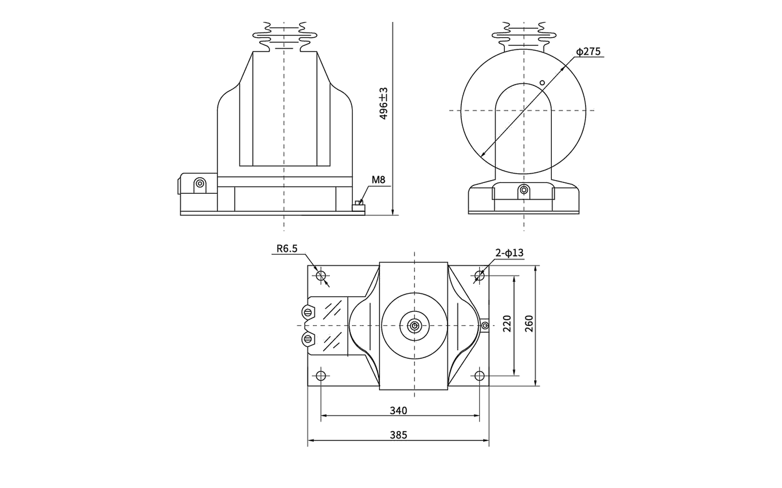
Key dimensions shown: Drawing values include 496±3 mm height, Ø275 body reference, 385/340/220 mm base references, M10, M8, R6.5 and 2-Ø13 mounting details.
Technical specification tables
JDZX9-35 — Rated voltage ratio and secondary output
Rated voltage ratio (kV)
0.2 (VA)
0.5 (VA)
Class 1 (VA)
Class 3 (VA)
0.2/0.2 or 0.2/0.5 (VA)
0.5/0.5 (VA)
6P (3P) (VA)
Max output (VA)
Rated insulation level (kV)
35000/√3 / 100/√3 / 100/3
120
300
500
800
/
/
150
1000
40.5/95/200
35000/√3 / 100/√3 / 100/√3 / 100/3
/
/
/
/
60/60 or 75/75
150/150
150
500/500
40.5/95/200
Overall dimension drawing
Check the overall dimensions, mounting centres, terminals and primary interface against the switchgear layout. Open the full-size view for closer inspection.
JDZX9-35 model-specific overall dimension drawing
Before ordering, confirm the selected ratio, accuracy class, burden, secondary arrangement, insulation level and cabinet interface for this model.
JDZX9-35 overall dimension drawing
CT and VT RFQ requirements
How to Specify an Indoor Current or Voltage Transformer
A complete inquiry starts with the electrical function and ends with the physical switchgear interface. Provide these five groups of data for new panels, replacement transformers or metering and protection upgrades.
01 Application and switchgear position
State whether the transformer is for current metering, current protection, earth-fault detection or voltage measurement, and identify the panel and installation position.
02 System data and CT or VT ratio
Provide system voltage and frequency, plus the CT primary/secondary current ratio or VT primary/secondary voltage ratio.
03 Accuracy class, burden and duty
State the metering or protection accuracy class, rated burden or output, and any protection or maximum-output requirement.
04 Cores, windings and terminals
Define the number of CT cores or VT secondary windings, terminal arrangement, connection method and any residual-voltage or relay winding.
05 Interface, quantity and delivery
Send the nameplate or project schedule, outline drawing, mounting dimensions, primary interface, cabinet position, quantity, destination and required delivery date.
Select by electrical duty
Select CT and VT Types for Metering, Protection and Earth-Fault Detection
Start with the circuit function, then verify ratio, accuracy, burden, secondary arrangement and installation interface. Similar housings do not make two transformers electrically or mechanically interchangeable.
01Current measurement and protection
Metering and protection current transformers
Check before selection
Primary and secondary current ratio, number of cores or windings
Metering or protection accuracy class and rated burden
Short-time thermal and dynamic current, plus busbar or cable interface
Models to compare
LZZBJ9-10A1, LZZBJ9-10Q B6, LMZK-10 and LMZC-10
LSY-107-75-65 and LZZB9-24/180b/2
LZZBJ9-35/250W1G1 for 40.5 kV insulation-class requirements
02Residual and earth-fault current
Zero-sequence current transformer
Check before selection
Required opening and conductor or cable arrangement
Relay type, relay-winding connection and setting current
Primary zero-sequence current and fixing-hole arrangement
Model to compare
LXK-80-240 is the zero-sequence CT in this indoor range
Use its relay connection table and dedicated dimension drawing
Confirm the protection scheme and earth-fault duty before quotation
03Single-phase voltage measurement
Single-phase voltage transformers
Check before selection
Primary and secondary voltage ratio and system frequency
Accuracy class, rated burden, maximum output and residual winding
Primary interface, terminals, grounding, mounting direction and clearances
Models to compare
JDZ(J)-10Q, JDZ10-10, JDZX10-10 and JDZX9-10Q
JDZ8-10R, JDZX18-10R1 and JDZX10-10R / JDZ16-10R
JDZX9-35 for 35 kV nominal systems and its listed winding options
04Three-phase voltage measurement
Three-phase voltage transformers
Check before selection
Three-phase connection and primary/secondary voltage ratio
Winding and terminal arrangement, accuracy class and maximum output
Grounding point, mounting surface and available cabinet envelope
Models to compare
JSZVR-10W and JSZV12A-10R
Confirm the required voltage ratio and output combination in the model table
Use a three-phase model only when it matches the circuit design
A model family is only the starting point. Confirm the exact ratio, accuracy class, burden, terminal arrangement and drawing before supply.
Applications and project scenarios
Indoor Instrument Transformers for New Switchgear, Replacement and Upgrades
The selection process changes with the project. New panels begin with circuit requirements; replacements begin with the installed nameplate and interface; protection or metering upgrades begin with the revised electrical duty.
01New equipment
New indoor switchgear panel production
Define the CT or VT duty from the primary and secondary circuit design.
Confirm ratio, accuracy class, burden, insulation level and frequency.
Set the mounting surface, primary interface, terminals and available cabinet envelope.
02Installed equipment
Existing CT or VT replacement
Capture the complete fitted nameplate, installed ratio and secondary configuration.
Model-specific technical data, overall dimension drawing and any required project, test or approval documents.
Commercial requirements
Quantity, destination, delivery date, trade terms and any technical or commercial assumption to be clarified.
Engineering and procurement checklist
Indoor CT and VT Data to Confirm Before Ordering
Engineering and purchasing should release the same model, electrical duty, secondary arrangement, cabinet interface and drawing revision. Use this checklist to prevent specification gaps between technical approval and the purchase order.
Indoor instrument transformer order confirmation checklist
Confirm before order
Information required
Why it matters
01Exact model and position
Complete model designation, quantity, cabinet designation and installed position.
Prevents a family name or visually similar housing from being treated as an exact match.
02CT or VT ratio
CT primary and secondary current ratio or VT primary and secondary voltage ratio.
The ratio defines the measurement or protection relationship and cannot be inferred from the enclosure.
03Accuracy, burden and duty
Accuracy class, rated burden or output, metering or protection function and maximum output where required.
Models with similar dimensions can be built for different metering and protection duties.
04Cores, windings and terminals
Number of CT cores or VT windings, secondary terminal labels, polarity and required connection arrangement.
The secondary configuration governs wiring, relay or meter inputs and terminal access.
05Insulation and project requirements
Insulation level, frequency, applicable project standard and required test or document scope.
Keeps the voltage class, project standards and approval documentation aligned.
A change to the mounting or primary connection can invalidate an otherwise correct electrical selection.
Select by installation environment
Choose Indoor or Outdoor Instrument Transformers
Use this page for epoxy-resin CTs and VTs installed inside medium-voltage switchgear or enclosed indoor equipment. Low-voltage instrument transformers are not included in this medium-voltage indoor range. For exposed outdoor service or outdoor combined transformers, continue to the outdoor range.
This pageIndoor Instrument Transformers18 indoor medium-voltage CT and VT models with technical specifications and overall dimension drawings.
All installation environmentsInstrument TransformersReview the complete instrument transformer range and choose the installation environment first.View all Instrument Transformers ↗
Outdoor installationOutdoor Instrument TransformersCompare outdoor current transformers, voltage transformers and combined instrument transformers.View Outdoor Instrument Transformers ↗
Indoor CT and VT selection FAQ
Indoor Current and Voltage Transformer FAQs
Concise answers for engineers and professional buyers specifying, replacing or ordering indoor instrument transformers for medium-voltage switchgear.
01What is the difference between an indoor current transformer and a voltage transformer?
An indoor current transformer (CT) converts primary current to a lower secondary current for metering or protection. An indoor voltage transformer (VT), also called a potential transformer (PT), converts system voltage to a lower secondary voltage for metering or protection. CTs and VTs serve different circuit functions and are not interchangeable.
02What information is required to select an indoor current transformer for MV switchgear?
Provide the system voltage and frequency, CT ratio, rated secondary current, metering or protection duty, accuracy class, burden, number of cores, short-time thermal and dynamic current requirements, primary conductor or window interface, terminals and mounting dimensions.
03What information is required to select an indoor voltage transformer for MV switchgear?
Provide the system voltage and earthing method, primary and secondary voltage ratio, frequency, accuracy class, rated burden or output, metering or protection duty, number and connection of secondary windings, residual-voltage winding where required, insulation level, terminals, primary interface and mounting dimensions.
04How do ratio, accuracy class and burden affect CT or VT selection?
Ratio matches the primary circuit quantity to the secondary input of the meter or relay. Accuracy class defines the required measurement or protection performance, while burden is the total VA connected to the secondary circuit. Confirm all three together because a model may offer different class and burden combinations by ratio or winding.
05Which IEC standards apply to medium-voltage current and voltage transformers?
IEC 61869-1 gives general requirements for instrument transformers above 1 kV. IEC 61869-2 adds requirements for inductive current transformers, and IEC 61869-3 covers inductive voltage transformers. State the project standard in the RFQ and confirm the standards listed for the selected model before ordering.
06When is a zero-sequence current transformer required?
Use a zero-sequence or core-balance CT when the protection design calls for residual-current or earth-fault measurement. For LXK-80-240, confirm the cable opening, relay type, relay-winding connection, relay setting current, primary zero-sequence current and mounting-hole arrangement.
07How do I select a replacement CT or VT for existing switchgear?
Do not select from a photograph or family name alone. Capture the complete nameplate, ratio, accuracy class, burden, secondary arrangement and polarity, insulation level, terminals, overall dimensions, mounting centres, primary interface and cabinet clearances, then compare them with the proposed model and drawing.
08What should be included in an RFQ for an indoor instrument transformer?
Include the project and application, new or replacement status, system voltage and frequency, CT or VT ratio, accuracy class, burden, cores or windings, terminal and mounting requirements, applicable standards and documents, quantity, destination, trade terms and required delivery date.