

Quick Takeaway
- Confirm the project duty and applicable requirements for MV Switching Equipment before selection or service work.
- Use recorded inspection and test evidence instead of unsupported assumptions.
- Keep the final acceptance, maintenance, and handover documents with the equipment record.
A load break switch can make and break load current; a disconnect switch cannot. That single functional boundary drives every selection, interlock, and installation decision in medium-voltage switchgear. The Load Break Switches selection context explains the product-family starting point, while the Disconnect Switches category covers the separate isolation role. Treating the two as interchangeable—or specifying one without confirming the other's role—creates either a safety gap or unnecessary cost.
| Attribute | Load Break Switch | Disconnect Switch |
|---|---|---|
| Makes/breaks load current | Yes | No |
| Interrupting medium | Air, SF₆, vacuum, or oil | Air gap only |
| Governing standard | IEC 62271-103:2021 | IEC 62271-102:2018 |
| Visible isolation required | Depends on design | Typically required |
| Position indication | Integral | Required per IEC 62271-102 |
| Interlock dependency | Often the primary switching device | Must be downstream of an interrupting device |
| Earthing switch integration | Common | Common |
| Voltage range (IEC) | Above 1 kV up to 52 kV | Above 1 kV |
| Typical location in circuit | Feeder switching, ring main | Bus isolation, transformer isolation, maintenance isolation |
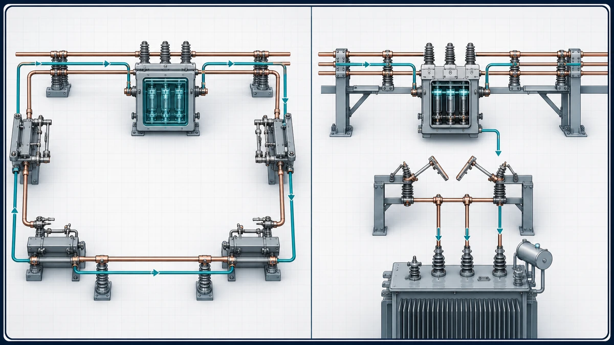
*Suggested figure: Single-line diagram contrasting a ring-main feeder loop using load break switches for normal switching versus a transformer bay using a disconnect switch downstream of a circuit breaker for maintenance isolation.*
—
What the Standards Actually Define
The IEC framework is precise on scope, and reading it carefully prevents misapplication.
IEC 62271-103:2021 covers AC switches and switch-disconnectors for their switching function, including indoor and outdoor installations above 1 kV up to 52 kV. The standard defines rated making and breaking current, distinguishing between load current switching and the special duties of cable charging current, line charging current, and small inductive current. A device tested under IEC 62271-103 has demonstrated it can interrupt those categories under defined conditions—the arc is managed by the interrupting medium and the mechanical design of the contact system.
IEC 62271-102:2018 applies to AC disconnectors and earthing switches above 1 kV. Its requirements concentrate on isolating distance, position indication, and interlocking—not on arc interruption, because the standard presupposes that current has already been interrupted by another device before the disconnector operates. The isolating distance requirement is the mechanical expression of that presupposition: the open gap must be visible or verifiably confirmed as sufficient to prevent re-energization.
The practical consequence is that a disconnect switch complying with IEC 62271-102 carries no verified interrupting rating. Operating it under load is outside its design envelope, regardless of whether the contacts could physically move. The arc energy that appears when a loaded circuit is broken by contacts not designed for interruption can cause contact welding, flashover, or explosive failure.
—
The Interrupting Mechanism and Why It Matters for Selection
A load break switch carries an arc-quenching mechanism—typically a puffer or rotating-arc geometry in SF₆, a vacuum interrupter bottle, or an air-blast arrangement—that controls the arc drawn between contacts as they separate under current. The interruption must occur before the arc energy damages contacts or causes a phase-to-phase or phase-to-ground fault. The rated breaking current, the number of rated operations, and the transient recovery voltage withstand all appear in the type-test record under IEC 62271-103.
A disconnect switch has no such mechanism. Its contacts are designed for mechanical durability across thousands of operations under zero or near-zero current, and the insulating gap dimensions are sized for the system's rated voltage. Position indication—required under IEC 62271-102—is not a convenience feature; it is the confirmation that the isolating gap has reached its rated open distance and that downstream work can begin safely.
This means the load break switch and the disconnect switch solve different problems. One manages energy during a switching operation; the other provides verified isolation after switching is complete. In many substation designs, both are present in series: the load break switch or circuit breaker opens first, then the disconnect switch is opened to establish the visible isolating gap required for a permit-to-work.
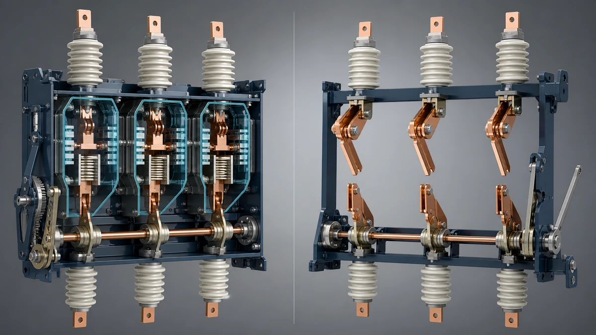
*Suggested figure: Cross-section comparison of a load break switch contact assembly (showing arc-quenching chamber) versus a disconnect switch contact assembly (showing open-air isolating gap with position indicator).*
—
Operating Sequence and Interlock Logic
The sequence dependency is the most failure-prone area in switchgear configuration. A disconnect switch opened under load—because an interlock failed, was defeated, or was never installed—can result in a personnel injury or equipment loss event. Interlock design is therefore not a procurement afterthought; it is a functional requirement that must be confirmed before equipment is specified.
IEC 62271-102 includes interlock requirements specifically to enforce correct sequence. The standard distinguishes between mechanical interlocks (which physically prevent out-of-sequence operation) and electrical interlocks (which rely on auxiliary contacts and control logic). Both have failure modes. Mechanical interlocks can be defeated by tool or by wear; electrical interlocks depend on the integrity of auxiliary contact circuits and control power availability.
For procurement purposes, the relevant questions are: what interlocking scheme is standard for the offered equipment, what are the defeat modes, and whether type-test evidence for the interlock under the relevant standard is available. For replacement decisions, the new device's interlock interface must be verified against the existing scheme—dimensional, electrical, and sequence compatibility are all independent checks.
Earthing switch integration adds a third position to the sequence: open-live, open-isolated (disconnect open), and earthed. IEC 62271-102 covers earthing switches within its scope, and the closing-onto-fault rating of the earthing switch is a separate rated quantity from the disconnect switch's voltage withstand. Both must be confirmed for the application.
—
Configuration Dependencies: Ring Main Units and Feeder Applications
In Ring Main Unit (RMU) configurations, load break switches are the normal switching devices for loop switching and feeder isolation. The compact geometry of an RMU integrates the load break switch, earthing switch, and often a fuse or circuit breaker in a single sealed or gas-insulated housing. The switching roles are defined by the RMU's internal single-line diagram, not by external interlock hardware.
Disconnect switches appear at substation bus level, transformer LV connections, and cable box connections where maintenance isolation is required after an upstream interrupting device has cleared the circuit. In a transformer bay, for example, the circuit breaker interrupts fault and load current; the disconnect switch—sometimes called an isolator in this context—then opens to provide the visible gap needed before transformer inspection or bushing replacement.
The risk in specifying for one configuration and installing in the other is not always obvious from nameplate data. A device rated under IEC 62271-103 may look identical to one rated under IEC 62271-102 from the outside. The arc-quenching mechanism is internal, and the type-test documentation is what distinguishes them. Procurement specifications should reference the applicable standard explicitly and require the type-test report.
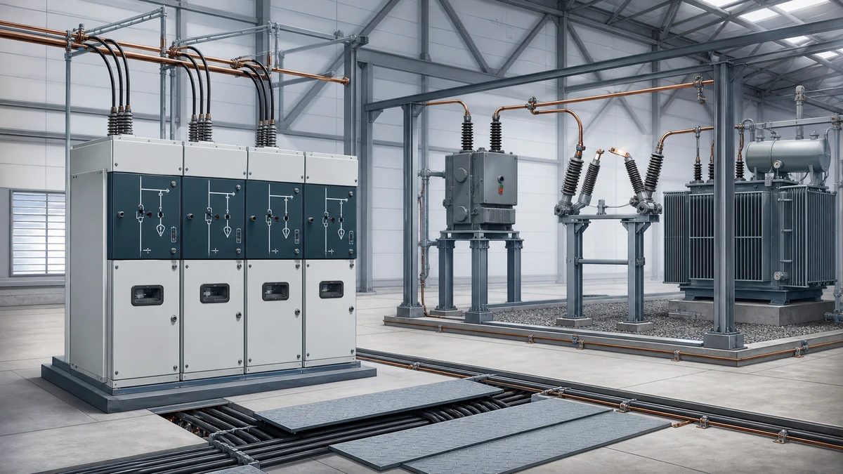
*Suggested figure: Schematic of a ring main unit showing load break switch positions for loop switching and feeder switching, compared to a transformer bay single-line showing circuit breaker upstream of disconnect switch for maintenance isolation.*
—
Selection and Verification Workflow
Before writing an RFQ or replacement specification, the following information must be in hand. Working through this sequence also identifies the questions to put to the manufacturer.
**System data:** Rated voltage (confirm against IEC voltage steps), maximum continuous current, prospective fault level at the point of connection, and the specific switching duty (load switching, cable charging, transformer magnetizing, or routine isolation only).
**Switching role confirmation:** Is the device required to make or break current? If yes, the device falls under IEC 62271-103 and must have a verified rated breaking current at least equal to the maximum load current it will interrupt in service. If the device is never operated under load, IEC 62271-102 applies, and the specification should confirm the interlock arrangement that enforces this.
**Interrupting medium:** SF₆ brings gas-handling obligations under local regulations; vacuum brings end-of-life interrupter replacement planning; air-break brings arc-flash energy calculations. The medium affects the maintenance program, not just the initial cost.
**Number of rated operations:** IEC 62271-103 defines mechanical and electrical endurance classes. A frequently switched feeder switch sees more operations than a disconnect switch opened only for annual maintenance. Specifying the endurance class incorrectly shortens contact life and changes the maintenance interval.
**Position indication and interlocking interface:** For disconnect switches, confirm that the position indicator meets IEC 62271-102 requirements and that the interlock interface is compatible with the existing or planned scheme. For replacement projects, confirm that auxiliary contact configuration, mounting dimensions, and terminal designations match the existing panel.
**Type-test evidence:** Request the type-test report, not a reference to the type-test number alone. The report shows the actual tested ratings and any deviations from the standard's standard conditions. For SF₆ devices, gas density monitoring and leak rate data from the type test are relevant to the maintenance specification.
For an equipment-specific review, send the documented duty, interface, and type-test evidence through Contact Us so the requested quotation remains tied to the declared application rather than to an assumed substitution.
—
Installation, Inspection, and Evidence Boundaries
Installation and commissioning of MV switchgear are governed by the equipment manufacturer's approved procedures, site-specific switching schedules, and applicable local regulations. The decision-relevant points at this stage are about evidence and verification, not live-operation steps.
Before energization, the items to confirm from documentation are: correct installation of the arc-quenching mechanism (for load break switches), correct gap dimension for the open position (for disconnect switches), interlock function verification at zero voltage, auxiliary contact alignment with the control circuit, and gas pressure or vacuum integrity check where applicable. These are checks against the installation record, not field adjustments—if any check fails, the manufacturer's procedure governs the response.
During periodic inspection, the comparison between measured contact resistance and the as-new factory record is the primary indicator of contact condition for a load break switch. For a disconnect switch, the isolating gap dimension and the position indicator function are the primary checks. Trending both over successive inspections gives earlier warning than a single-point measurement.
Any observed deviation—contact pitting beyond the manufacturer's threshold, gas pressure below the alarm level, a sluggish or incomplete interlock operation—is an escalation trigger to the manufacturer or a qualified service organization. Model-specific approved procedures govern any adjustment, torque verification, gas handling, or contact replacement. Working from generic information in those areas introduces risk that the type-tested performance was designed to eliminate.
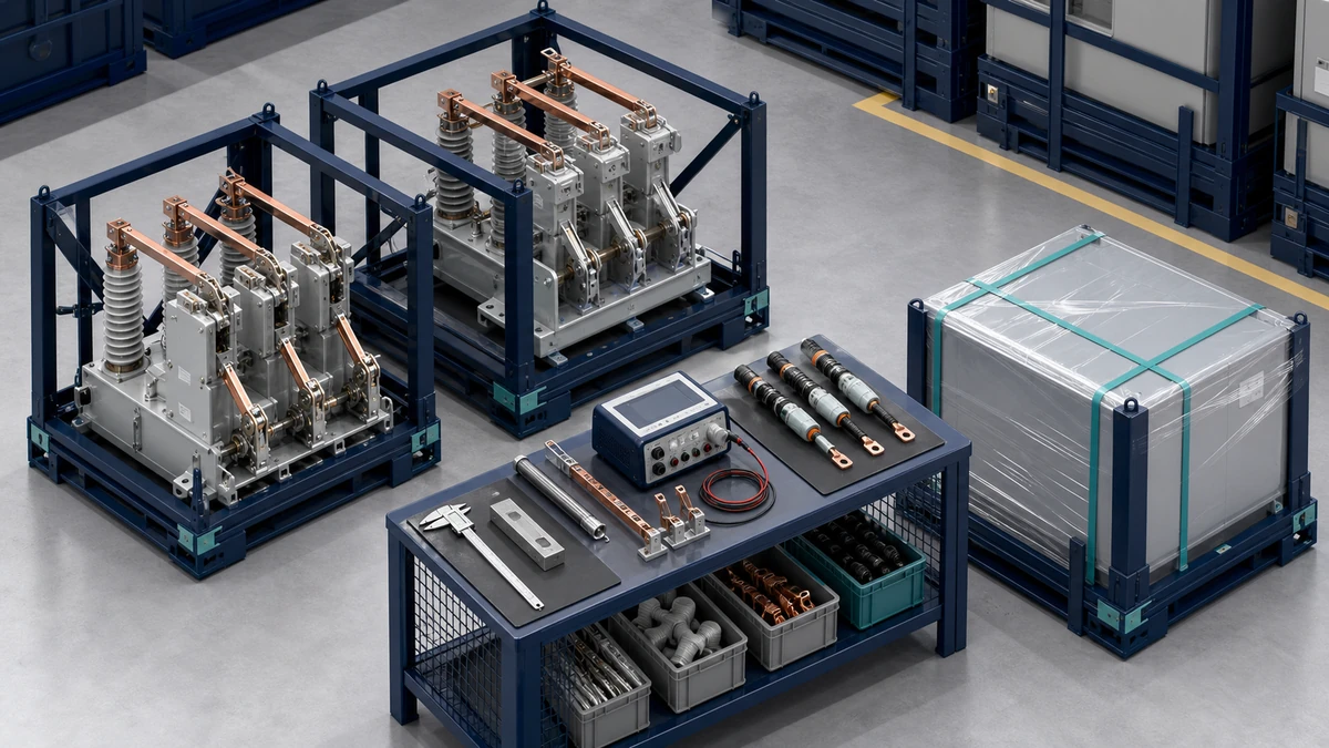
*Suggested figure: Inspection and verification checklist flow for a load break switch (focusing on interrupting mechanism, contact resistance, and gas/vacuum integrity) versus a disconnect switch (focusing on isolating gap, position indication, and interlock function).*
—
Replacement Decisions: What Changes When You Change One
Replacing a like-for-like device in an existing bay is less straightforward than it appears. Even when the replacement carries the same standard reference, differences in physical dimensions, auxiliary contact arrangement, and interlock interface can require panel modifications that were not in the project scope.
For a load break switch replacement, the rated making current, rated breaking current, and rated short-time withstand current must all be confirmed against the existing protection coordination study—not just the system nominal voltage and current. If the fault level has increased since original installation, the original device's ratings may no longer be adequate, and a replacement in kind would perpetuate the gap.
For a disconnect switch replacement, the isolating distance of the new device must meet or exceed the original, and the interlock interface must be verified before any panel wiring is changed. If the original device used a specific key-interlock scheme, the replacement's compatibility with that scheme is a mechanical and keying question, not just a dimensional one.
Mixing devices from different manufacturers in a coordinated interlock scheme requires the scheme designer's review. Interlock compatibility is not implied by standard compliance—two devices both compliant with IEC 62271-102 may have incompatible auxiliary contact timing or key-interlock configurations.
—
FAQ
What is the core functional difference between a load break switch and a disconnect switch?
A load break switch is designed and tested to make and break load current under the conditions defined in IEC 62271-103. It contains an arc-quenching mechanism that controls the arc energy during contact separation. A disconnect switch, covered by IEC 62271-102, is designed to provide a verified isolating gap after current has already been interrupted by another device. It has no arc-quenching capability and must not be operated under load.
What is the IEC standard that governs load break switches?
IEC 62271-103:2021 covers AC switches and switch-disconnectors for their switching function, including indoor and outdoor installations above 1 kV up to 52 kV. It defines rated making and breaking currents and the specific switching duties the device is verified to perform.
What is the IEC standard that governs disconnect switches?
IEC 62271-102:2018 applies to AC disconnectors and earthing switches above 1 kV. Its requirements address isolating distance, position indication, and interlocking—the features that confirm the circuit is de-energized and the gap is sufficient for safe downstream work.
What is the risk of operating a disconnect switch under load?
A disconnect switch has no arc-quenching mechanism. If operated under load, the arc drawn between the separating contacts cannot be controlled. The result can be contact welding, phase-to-phase flashover, or explosive failure. This is why IEC 62271-102 emphasizes interlock requirements: the standard assumes the disconnect switch will only be operated after current has been interrupted by an upstream device.
What is the role of position indication on a disconnect switch?
IEC 62271-102 requires position indication because the open position of the disconnect switch is the basis for issuing a permit-to-work. Personnel working on downstream equipment depend on confirmed isolation. Position indication—whether visual, mechanical flag, or electrical auxiliary contact—is the means of verifying that the isolating gap has reached its rated open distance, not just that the operating mechanism has moved.
What is a switch-disconnector and how does it relate to these two devices?
A switch-disconnector combines both functions in a single device: it can make and break load current (the switching function under IEC 62271-103) and provides a verified isolating gap in the open position (the disconnecting function under IEC 62271-102). It is common in compact MV switchgear where separate devices would be impractical. The type-test record must confirm both functions; compliance with one standard alone does not imply the other.
What is the earthing switch's relationship to the disconnect switch?
Earthing switches are covered within IEC 62271-102 alongside disconnectors. In a maintenance isolation sequence, the disconnect switch opens to establish the isolating gap, and then the earthing switch closes to ground the isolated section before personnel access. The earthing switch has a separate rated quantity—its rated short-circuit making current—which must be confirmed against the system fault level. It is not the same rating as the disconnect switch's short-time withstand current.
What is the key data needed before issuing an RFQ for either device?
The minimum data set is: rated voltage, maximum continuous current, prospective fault level at the point of installation, the specific switching duty (load switching or isolation only), the interrupting medium preference (if any), the required number of rated operations, the interlock interface requirements, and the position indication requirements. For replacement projects, add the existing device's dimensional envelope and auxiliary contact configuration. Without this data, the manufacturer cannot confirm type-test coverage for the application.

