

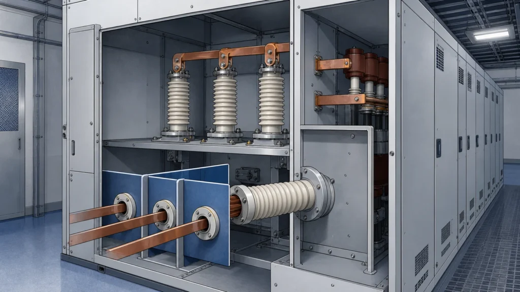
Quick Takeaway
- Confirm the project duty and applicable requirements for Switchgear Insulation Components before selection or service work.
- Use recorded inspection and test evidence instead of unsupported assumptions.
- Keep the final acceptance, maintenance, and handover documents with the equipment record.
Every switchgear insulator replacement or procurement request starts with the same question: what exactly is installed? The answer requires identifying the insulator's functional type, its mounting arrangement within the switchgear assembly, and the mating interface dimensions that govern fit. Getting any one of those three wrong means the replacement part either does not physically install, does not maintain the assembly's documented insulation coordination, or both.
This guide provides a structured method for collecting and verifying the identification and drawing data needed before issuing an RFQ or approving a substitute. It does not cover dielectric testing, clearance validation, or creepage approval, all of which require separate engineering review against the documented switchgear assembly per IEC 62271-200:2021. Related evidence-led guidance is collected in the Technical Articles library.
Why Assembly Context Governs Insulator Identification
An insulator inside metal-enclosed switchgear is not an abstract, interchangeable commodity. IEC 62271-200:2021 applies to prefabricated AC metal-enclosed switchgear and controlgear assemblies, and its scope means every insulator record must be reviewed in relation to the documented switchgear assembly rather than as a standalone catalog item. Two insulators with identical material, voltage class, and external dimensions can serve entirely different functions inside the same switchgear lineup, and swapping them introduces risk that is invisible until the assembly is re-tested or fails.
This assembly-level dependency is the single most important principle in switchgear insulator identification. It determines every step that follows: the type categories that matter, the interface data to collect, and the verification checks to run before purchasing.
Functional Types and Where They Appear
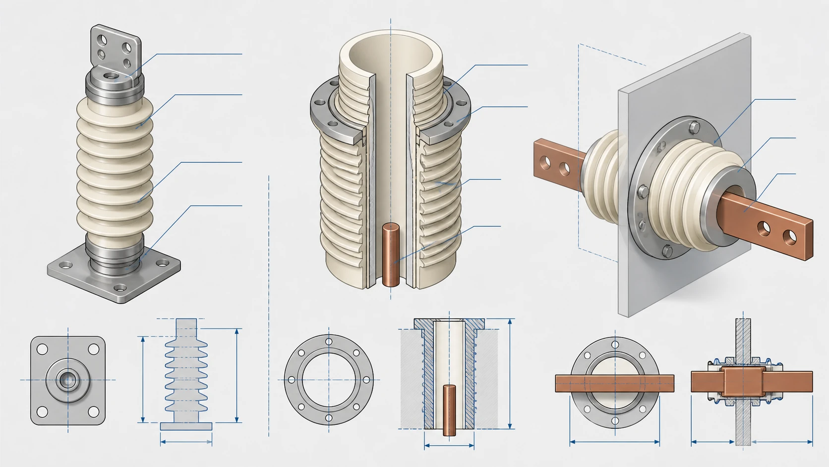
Metal-clad and metal-enclosed switchgear designs use several distinct insulator types. Schneider Electric's SureSeT MV indoor switchgear product documentation is a useful reference because it explicitly names and separates five functional categories within one switchgear design. These categories generalize well across OEM platforms, even though part numbers and geometries differ. The MV Switching Equipment category gives the wider equipment context without establishing a substitute part.
| Functional Type | Typical Location | Primary Role |
|---|---|---|
| Primary-bushing insulating tube | Cable or busbar entry point through a grounded barrier | Carries the primary conductor through a metal partition while maintaining phase-to-ground insulation |
| Switchgear standoff insulator | Chassis or frame mounting point for bus or breaker cradle | Supports a live conductor or assembly at a fixed standoff distance from the grounded enclosure |
| Auxiliary-device standoff insulator | Instrument transformer, relay, or sensor mounting | Provides mechanical support and insulation clearance for secondary or control devices |
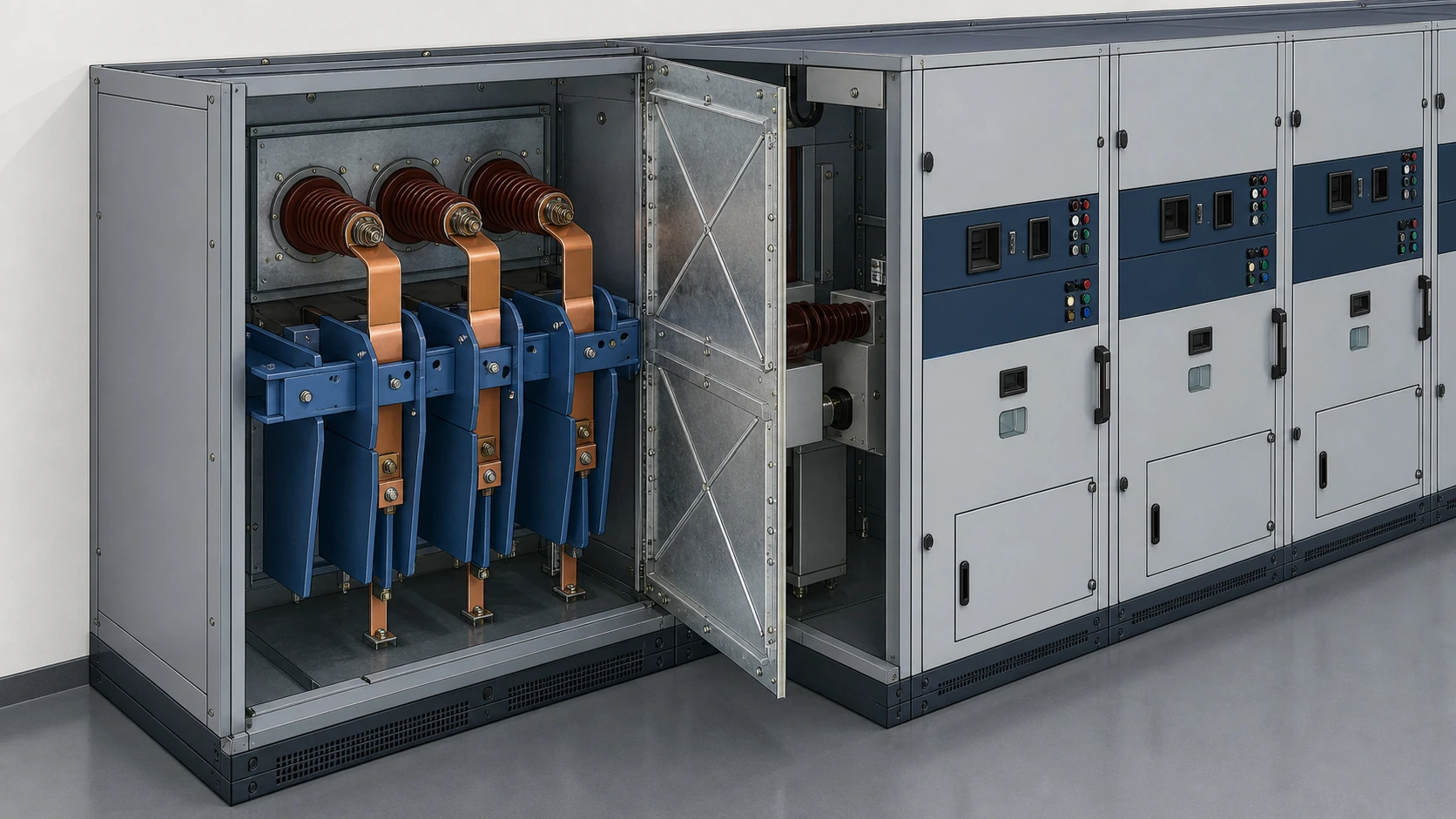
| Bus pass-through barrier | Compartment boundary where bus transitions between sections | Maintains compartment segregation (LSC category) while permitting the bus conductor to pass through |
| Material-group-specific insulator | Any of the above, distinguished by resin system or filler | Matches the material record documented for the assembly's type-tested insulation coordination |
The first identification task is to determine which of these functional roles the insulator serves. A standoff insulator supporting a breaker cradle has different mechanical load requirements, bolt patterns, and creepage profiles than a bus pass-through barrier of the same voltage class. Confirming the functional type before collecting dimensions prevents the common error of matching geometry while mismatching function.
Data Points to Collect Before Requesting a Replacement
A complete identification record for one insulator position contains three layers of data: assembly identity, insulator identity, and interface geometry. Missing any layer forces the supplier to guess, which delays quoting and increases the chance of a misfit. When the position is in a withdrawable breaker compartment, the Vacuum Circuit Breakers category can help name the related equipment context; the as-built drawing remains decisive.
**Assembly identity.** Record the switchgear OEM, product family, voltage and current ratings of the specific assembly, the serial number or type-test report reference, and the compartment or position where the insulator is installed. Under IEC 62271-200:2021, the insulator's validity is tied to the assembly, so this context is not optional background; it is the primary reference.
**Insulator identity.** Capture the OEM part number (stamped, labeled, or from the parts list in the switchgear instruction manual), the material designation (e.g., cycloaliphatic epoxy, SMC, BMC, cast resin with alumina filler), and the functional type from the table above. If the part number is unreadable, photograph the insulator in place with a scale reference and note its color, surface finish, and any visible date or batch code.
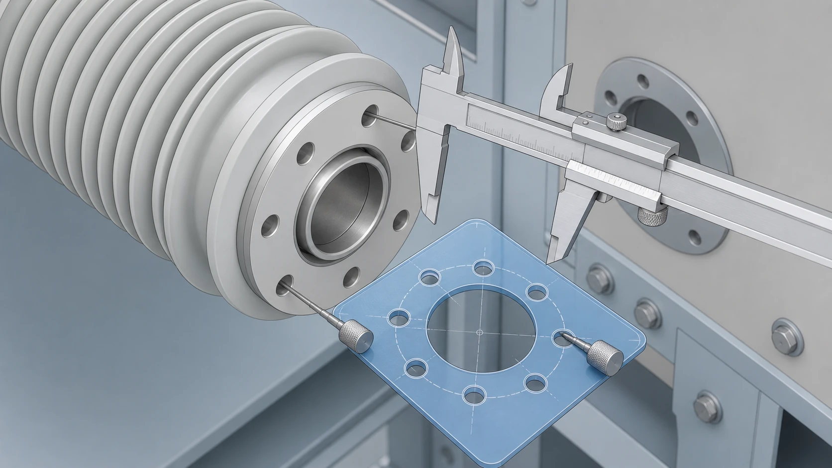
**Interface geometry.** This is the data that determines physical fit. Collect bolt-hole pattern (number, diameter, pitch circle diameter), mounting-face flatness and surface area, conductor bore or pocket diameter and depth, any keying features or alignment pins, and the overall envelope dimensions (height, maximum outer diameter or width, and creepage path length if molded ribs are present). These dimensions come from the OEM's installation or assembly drawing. If the drawing is unavailable, field measurement with calibrated instruments is the fallback, but the drawing remains the authoritative source.
Reading an Insulator Drawing for Interface Verification
OEM insulator drawings typically present three categories of information: form dimensions, material callout, and mounting interface detail. For identification and procurement purposes, the mounting interface detail is the section that matters most and the one most often overlooked.
Look for the bolt-circle or fastener pattern first. This is the mechanical constraint that physically prevents a wrong-geometry insulator from being installed, or worse, allows it to be installed with only partial engagement. Compare the drawing's bolt-circle PCD against the switchgear frame's mating holes. A 2 mm discrepancy on a four-bolt pattern can result in binding, stress cracking, or incomplete seating that degrades the insulation boundary.
Next, confirm the conductor interface. For a primary-bushing insulating tube, this is the bore that accepts the conductor or the molded pocket that mates with a plug-in contact. For a standoff insulator, it may be a flat mounting pad or a threaded insert. The drawing should dimension these features with tolerances. If tolerances are absent, flag the drawing as incomplete in your RFQ.
Finally, check the material note. The material group recorded on the drawing must match the material group documented for the assembly. Schneider Electric's SureSeT documentation explicitly tracks material groups as a separate identification axis, and this practice reflects a broader industry requirement: substituting a different resin system can change the insulator's tracking resistance, arc behavior, and aging characteristics in ways that invalidate the assembly's type-test basis.
Common Identification Errors and How to Avoid Them
**Matching by voltage class alone.** Two 12 kV-rated insulators from the same OEM catalog may have different creepage profiles, mounting interfaces, and material groups because they serve different functional types within different switchgear families. Voltage class is necessary but nowhere near sufficient.
**Ignoring compartment segregation category.** Bus pass-through barriers contribute to the assembly's loss-of-service continuity (LSC) classification under IEC 62271-200. Replacing a barrier insulator with one that fits geometrically but does not restore the documented partition integrity can downgrade the entire assembly's LSC category. This is an assembly-level consequence that a standalone insulator datasheet will not flag.
**Using field measurements without drawing confirmation.** Field dimensions of a worn, contaminated, or thermally aged insulator may differ from the nominal drawing dimensions. Always cross-reference field measurements against the OEM drawing or parts list. If neither is available, state that clearly in the RFQ so the supplier knows the dimensions are measured, not nominal.
**Treating material as cosmetic.** Color and surface texture vary between resin systems, but they are not reliable identifiers on their own. Two visually similar insulators can use different filler compositions. The material callout on the drawing or parts list is the authoritative record.
Verification Workflow Before Issuing an RFQ
The following sequence consolidates the identification and verification steps into a single pass. It is designed to produce an RFQ package that a supplier can quote without follow-up questions.
1. Confirm the switchgear assembly identity: OEM, family, serial number, applicable type-test report.
2. Locate the insulator on the assembly general arrangement drawing or compartment layout. Record its position designation.
3. Identify the functional type using the categories above.
4. Retrieve the OEM part number from the parts list, nameplate, or instruction manual.
5. Obtain the insulator's installation or detail drawing. Extract the interface geometry data: bolt pattern, conductor bore, envelope, and material callout.
6. If the original drawing is unavailable, measure the installed insulator and the mating frame interface independently, then cross-check for consistency.
7. Photograph the insulator in situ (showing mounting context), the nameplate or stamp, and any visible damage or aging.
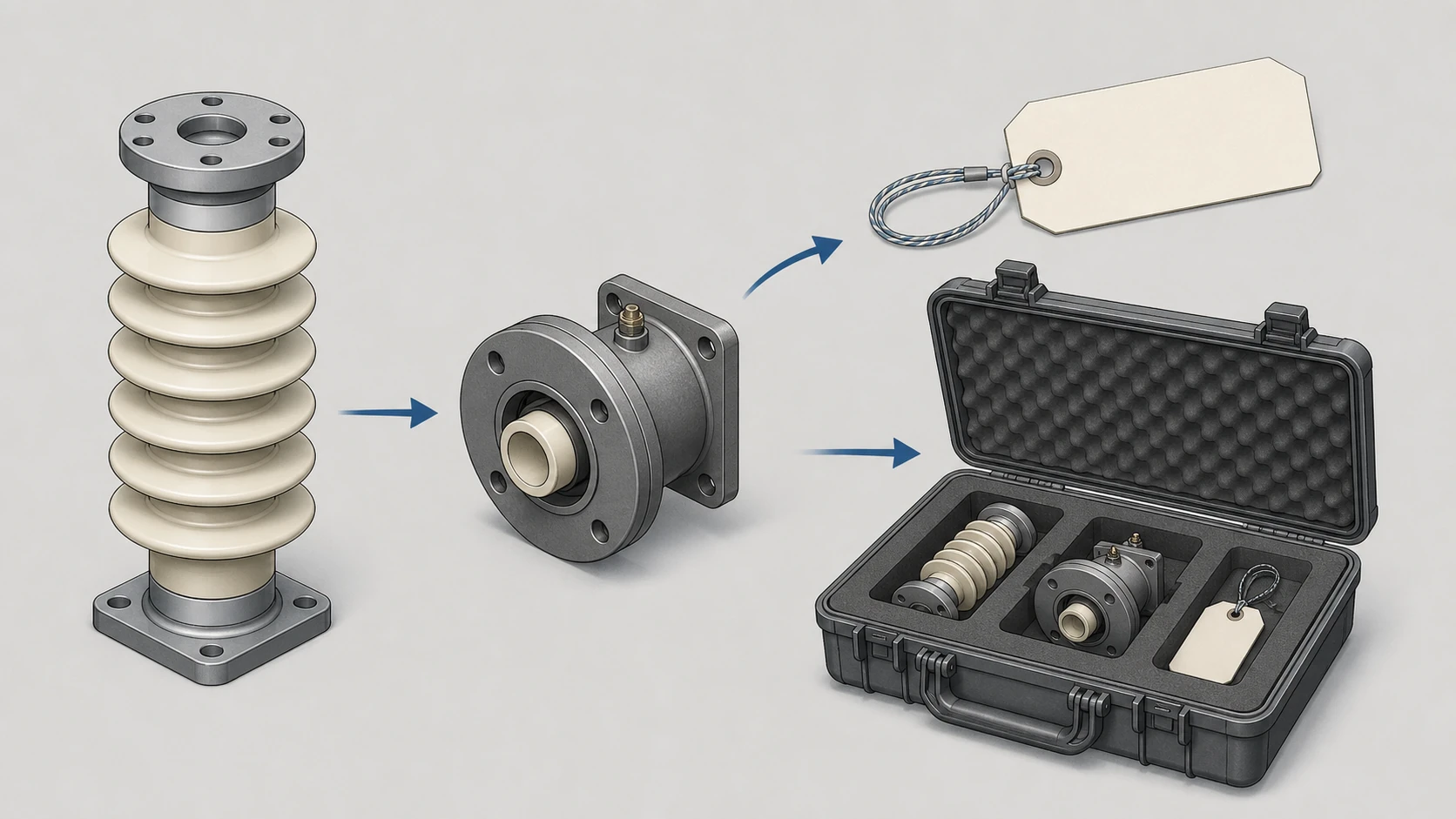
8. Compile the data into a single identification sheet: assembly context, functional type, part number, interface dimensions, material, and photographs. Attach the drawing if available.
9. State explicitly in the RFQ whether the data is drawing-confirmed or field-measured, and whether the replacement must be OEM-identical or whether alternatives from the relevant product range will be evaluated against the same interface and material specification.
Step 9 is where procurement and engineering intersect. A field-measured, non-OEM replacement requires additional engineering review to confirm that the substitute maintains the assembly's documented insulation coordination. That review is outside the scope of this identification guide, but flagging the data source up front prevents downstream surprises.
When to Escalate Beyond Identification
Identification and drawing data collection are necessary first steps, but they are not the whole story. Escalate to a qualified engineer or the OEM when any of the following conditions apply:
- The insulator shows signs of tracking, erosion, discoloration beyond surface contamination, or mechanical cracking.
- The original OEM part number is discontinued and no documented cross-reference exists.
- The switchgear assembly's type-test report is unavailable, making it impossible to confirm the insulator's role in the assembly's insulation coordination.
- The proposed replacement changes material group, creepage profile, or mounting arrangement relative to the original.
- The insulator is part of a bus pass-through barrier that contributes to compartment segregation (LSC classification).
In all these cases, model-specific approved procedures and the OEM's engineering documentation govern the next steps. This guide's scope ends at identification and data collection.
FAQ
What is the first step in switchgear insulator identification?
Confirm the switchgear assembly identity: OEM, product family, serial number, and the compartment or position where the insulator is installed. Under IEC 62271-200:2021, an insulator's record must be reviewed in relation to the documented switchgear assembly, so assembly context is the mandatory starting point before any dimensional or material data is collected.
What is the difference between a standoff insulator and a bus pass-through barrier?
A standoff insulator supports a live conductor or device at a fixed distance from the grounded enclosure, carrying mechanical load and maintaining clearance. A bus pass-through barrier serves a compartment segregation function: it allows the bus conductor to pass between switchgear sections while maintaining the partition integrity that defines the assembly's loss-of-service continuity (LSC) category. Schneider Electric's SureSeT documentation lists these as separate functional categories with distinct identification records, and the distinction matters because replacing one type with the other's geometry can compromise compartment ratings even if the part physically fits.
What is the role of material group in insulator identification?
Material group identifies the resin system and filler composition used in the insulator. It is tracked as a separate identification axis because substituting a different material can change tracking resistance, arc behavior, and long-term aging, potentially invalidating the assembly's type-test basis. The material callout on the OEM drawing or parts list is the authoritative reference; visual appearance alone is not a reliable indicator.
What is the minimum data needed for an insulator RFQ?
A complete RFQ package includes the switchgear assembly identity (OEM, family, serial number), the insulator's functional type, the OEM part number, the interface geometry (bolt pattern, conductor bore, envelope dimensions), the material callout, and at least one in-situ photograph. The RFQ should also state whether the dimensional data is drawing-confirmed or field-measured, because field-measured replacements require additional engineering review before approval.
What is the risk of identifying an insulator by voltage class alone?
Voltage class is a necessary but insufficient identifier. Within the same voltage class and even the same OEM catalog, insulators differ by functional type, mounting interface, creepage profile, and material group. Two 12 kV-rated parts may be completely non-interchangeable. Relying on voltage class alone risks procuring a part that either does not physically fit or fits but does not maintain the assembly's documented insulation coordination.

