

Quick Takeaway
- Confirm the project duty and applicable requirements for the product range before selection or service work.
- Use recorded inspection and test evidence instead of unsupported assumptions.
- Keep the final acceptance, maintenance, and handover documents with the equipment record.
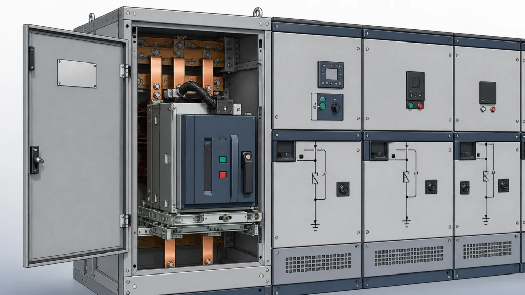
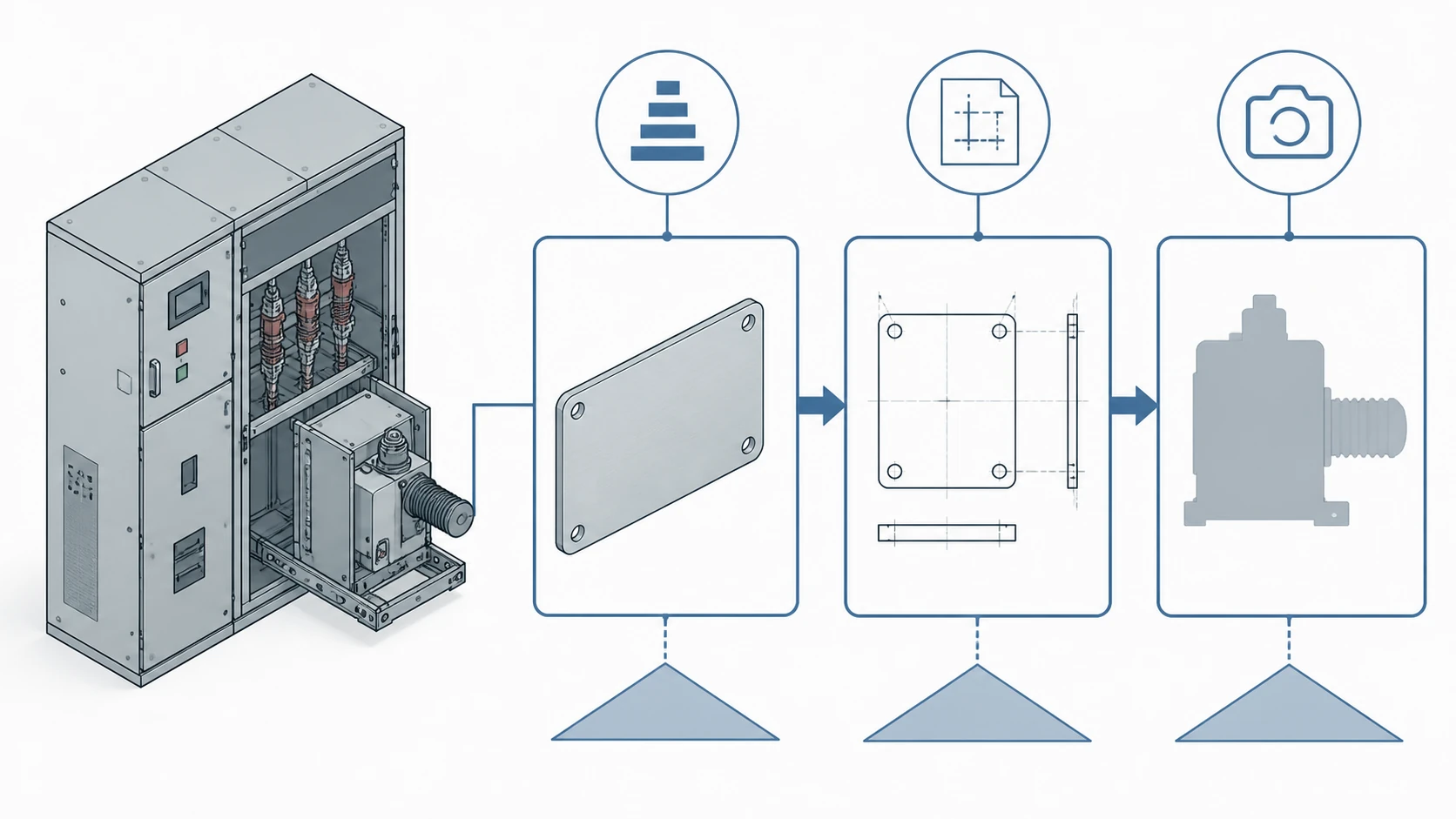
A single nameplate photograph can start the identification of a medium-voltage switchgear spare part, but it cannot finish it. The nameplate records the assembly's order number, serial number, and drawing number — enough to locate the configured bill of material — while the drawing set is the only document that relates a named part to its electrical ratings, mechanical interfaces, and position within the assembly. A photograph of the physical part adds shape, wear condition, and mounting context, yet it carries no configuration authority on its own. The correct approach is to collect all three forms of evidence in a defined sequence, let each one do only the job it can do, and escalate to the OEM or a qualified engineer whenever the records conflict or a gap appears.
The Problem with Single-Source Identification
Procurement teams routinely receive a request that amounts to "I need this part," accompanied by one piece of evidence: a smartphone photo of a worn contact, a hand-copied nameplate serial number, or a partial drawing excerpt. Each piece is useful. None is sufficient alone.
The risk is not academic. A vacuum circuit-breaker pole assembly and a load-interrupter assembly can share similar external dimensions yet differ in arc-interruption medium, rated short-circuit current, and mechanical interlock geometry. Ordering by visual match alone can place an incompatible component inside a rated and type-tested enclosure, voiding the assembly's compliance basis and creating a safety exposure. Ordering by nameplate number alone can deliver the correct assembly-level replacement while missing a running design change that altered an internal sub-component. Ordering by drawing alone can deliver the correct part on paper while missing physical damage to the housing or bus interface that changes the scope of the replacement.
The evidence hierarchy exists to close these gaps systematically.
Why Assembly Context Governs Part Identity
IEC 62271-200:2021 applies to prefabricated AC metal-enclosed switchgear and controlgear assemblies. Its scope matters here not because it prescribes a part-ordering procedure, but because it frames the switchgear as a type-tested or partially type-tested assembly whose ratings depend on the combination of components, partitions, bus arrangements, and enclosure geometry. A spare part is not a standalone device in this context; it is a constituent whose electrical clearances, mechanical fit, and thermal performance were validated as part of a specific assembly configuration.
This means the identification record for any spare part must preserve the assembly context: which switchgear lineup, which cubicle position, which functional unit, and which revision of the assembly drawing set the part belongs to. Strip away that context — by relying on a part photograph alone, for example — and the record cannot confirm that the replacement will maintain the assembly's rated performance.
The Three Evidence Types and What Each One Proves
For a component inside an MV Switching Equipment lineup, keep this evidence set with the specific cubicle record. Related evidence-led guidance is collected in the Technical Articles library.
| Evidence type | What it establishes | What it cannot establish |
|---|---|---|
| **Nameplate image** | Assembly identity: manufacturer, order number, serial number, drawing number, rated voltage, rated current, date of manufacture | Internal sub-component revision, interface dimensions, or wiring configuration |
| **Drawing set** | Configured bill of material, positional relationships, control schematics, wiring diagrams, floor plans, elevations, one-line diagrams | Current physical condition, field modifications not captured in as-built drawings |
| **Photograph of the part** | Physical condition, approximate dimensions, mounting orientation, visible damage, labelling on the component itself | Rated values, material specification, internal construction, compatibility with adjacent parts |
Each column in this table defines a boundary. Crossing that boundary — treating a nameplate as proof of a sub-component's revision, or treating a photograph as proof of a rating — is where mis-identification begins.
Evidence Step 1: Capture a Complete Nameplate Record
ABB's documentation for BreakMaster medium-voltage load-interrupter switchgear identifies order number, serial number, and drawing number on the equipment nameplate as the information to provide whenever assembly identification is required. This guidance generalises across OEMs: the nameplate is the starting identity record, not standalone proof of a component interface.
A complete nameplate capture means a legible photograph — or a verified transcription — of every field on the main assembly nameplate and, where accessible, on the nameplate of the functional unit or withdrawable component that contains the part in question. "Legible" is the operative word. A partial serial number or an unreadable date code forces the identification process into guesswork.
Practical guidance for the field:
- Photograph the nameplate straight-on, with adequate lighting and a reference object for scale.
- If the nameplate is corroded or paint-covered, note which fields are unreadable rather than guessing their content.
- Record the nameplate of the specific cubicle, not only the lineup nameplate, because ratings and configurations can differ between positions in the same switchgear row.
- Transmit the image at original resolution; compressed thumbnails routinely lose the last digits of serial numbers.
The nameplate gives procurement a starting key to request the correct drawing set from the OEM or from the facility's document archive.
Evidence Step 2: Locate and Review the Drawing Set
Schneider Electric states that customer order drawings for products such as SureSeT MV indoor switchgear include floor plans, elevations, one-line diagrams, bills of material, control schematics, and wiring diagrams. This scope of documentation is typical for engineered-to-order MV switchgear across manufacturers. The drawing set is the source that relates a named part to a configured assembly — it answers the question "which exact variant of this part was specified for this specific switchgear, in this specific cubicle, at this specific revision?"
Drawing review serves two identification purposes:
1. **Bill-of-material confirmation.** The BOM lists the manufacturer part number, description, and quantity for every constituent. Cross-referencing the nameplate's order or drawing number against the BOM isolates the correct part number and revision.
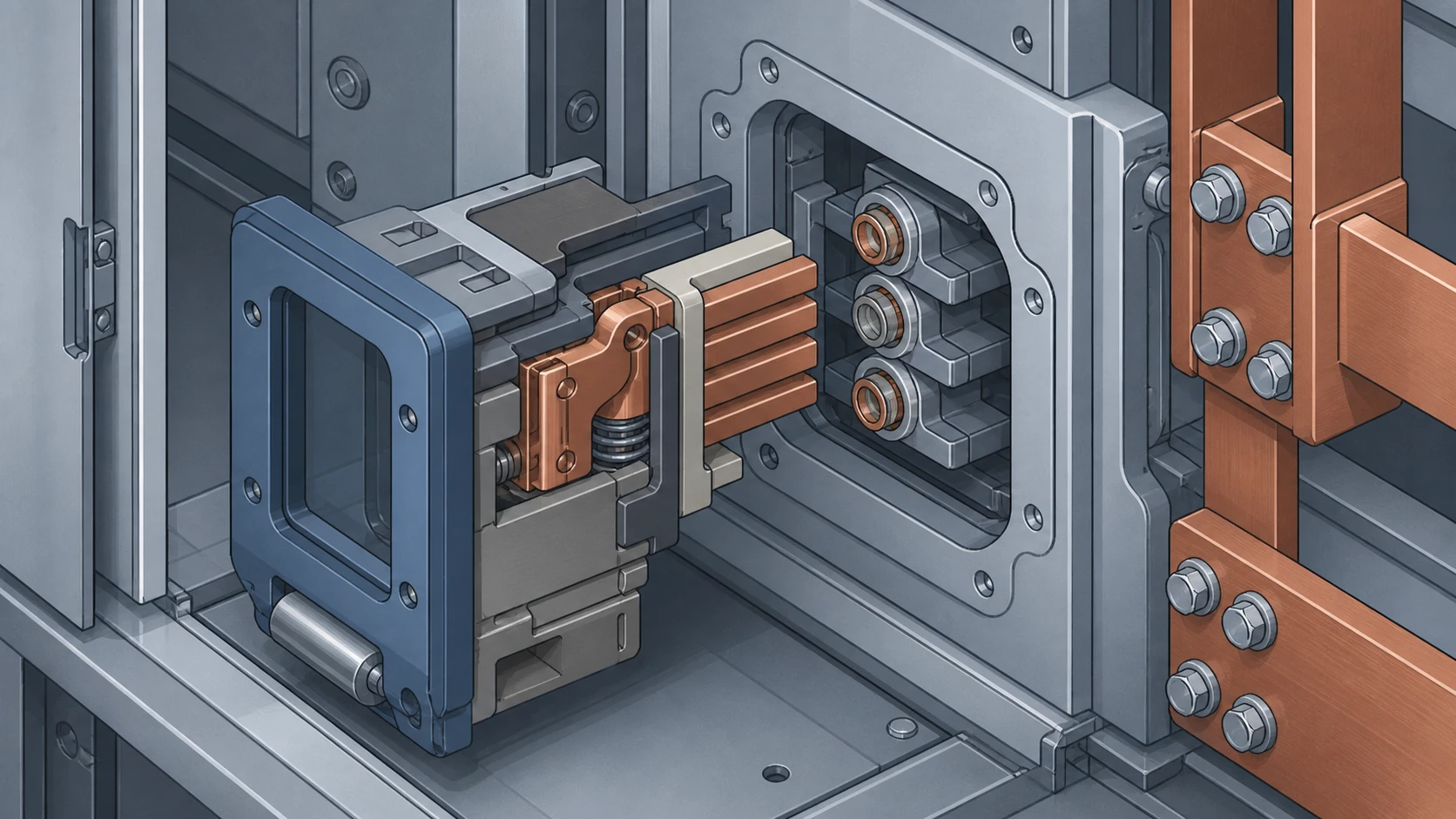
2. **Interface verification.** The elevation drawings, control schematics, and wiring diagrams show how the part connects mechanically and electrically to adjacent components. A replacement part must match these interfaces, not merely carry the same catalogue designation, because the same catalogue item can ship in multiple configurations depending on the assembly design.
If the drawing set is unavailable — lost in a facility transition, never transferred from the original owner, or held by an OEM behind a service agreement — the identification process stalls at a defined point. The correct response is to request the drawings from the OEM using the nameplate data, not to skip ahead and order by photograph.
When as-built drawings are available but their revision history is incomplete, flag this gap explicitly in the RFQ. A part ordered against a superseded drawing revision may arrive with obsolete mounting holes, outdated bushing dimensions, or deprecated control wiring.
Evidence Step 3: Photograph the Physical Part in Position
The photograph of the physical part serves the drawing set, not the other way around. Its role is to confirm visible condition, to document the installed orientation and adjacent interfaces, and to capture any field-applied labels, modifications, or damage that the drawing set would not reflect.
Useful photographic evidence includes:
- A full-component view showing mounting position relative to the enclosure or functional unit.
- Close-ups of connection interfaces: bushing faces, bolted joints, plug-in contacts, control terminal strips.
- Any visible damage, discolouration, arc tracking, or mechanical deformation.
- Field-applied labels, tags, or markings that may indicate a prior replacement or modification.
Photographs do not carry configuration authority. A photo that "looks like" a particular part number is not evidence that it is that part number. Two visually similar moulded-case components can differ in interrupting rating, contact material, or spring mechanism. The photograph's value is that it catches what the drawing set misses — physical reality — while the drawing set catches what the photograph misses — engineering intent.
When the Evidence Conflicts
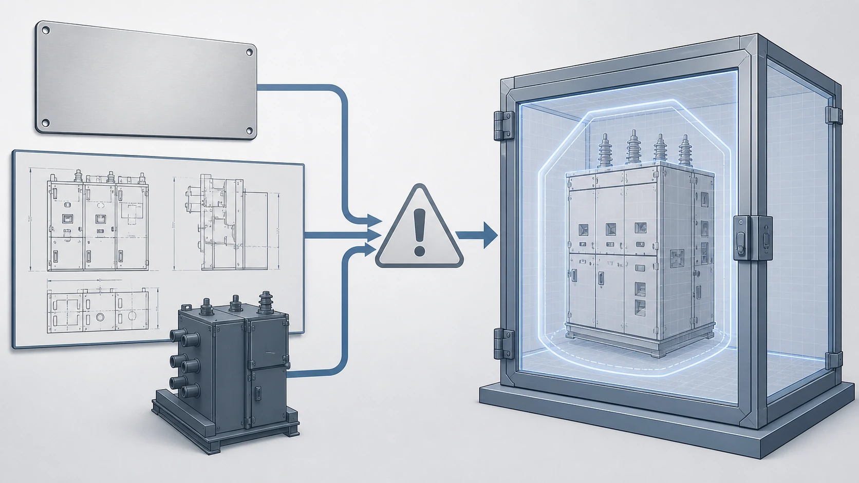
Conflicts between the three evidence types are common and informative. Each conflict pattern points to a specific underlying cause.
**Nameplate says one thing, drawing says another.** This usually means the assembly was modified after manufacture — a retrofit, an uprate, or a running design change — and either the nameplate or the drawing was not updated. Resolve by requesting the OEM's change-order history for the serial number.
**Drawing says one thing, photograph shows another.** This usually means a field replacement was performed without updating the as-built drawings, or the part has degraded beyond its documented configuration. Resolve by comparing the photographed part against both the current BOM entry and any available maintenance records.
**Nameplate is unreadable or missing.** This removes the primary key for the entire identification chain. Resolve by working from secondary identifiers: the cubicle position in the facility's single-line diagram, any surviving sub-component nameplates, or the OEM's records keyed to the site's original purchase order.
In every conflict scenario, the correct action is to document the discrepancy and escalate to the OEM or a qualified engineer before issuing a purchase order. Guessing which evidence source is "probably right" transfers the engineering risk from the identification process to the operating installation.
Building the Identification Package for an RFQ
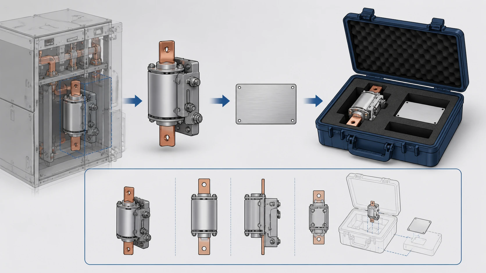
Before contacting a supplier or submitting a request for quotation, assemble a single identification package that contains:
- The nameplate image or verified transcription, noting any unreadable fields.
- The relevant drawing set pages: BOM, elevation or sectional view showing the part in position, and control schematic if the part has electrical terminations.
- Photographs of the installed part showing condition and interfaces.
- A written note of any conflicts between the three evidence sources and how they were resolved or flagged.
- The assembly's rated voltage, rated normal current, and rated short-time withstand current as stated on the nameplate or in the drawing set — not estimated from the part's appearance.
This package lets the supplier confirm part compatibility at the assembly level, not just at the catalogue level. It also protects the buyer: if the supplier delivers an incompatible part, the identification package establishes what information was provided and where the mismatch originated.
Boundaries of This Guide
This guide covers the evidence hierarchy for identifying an MV switchgear spare part. It does not replace model-specific engineering review. Rated values, torque specifications, gas-handling procedures, protection relay settings, and interlock adjustments are governed by the OEM's approved procedures for the specific switchgear model and revision. A document set — no matter how complete — never substitutes for that review when the replacement involves a safety-critical interface or a change in rated capability.
FAQ
What is the most reliable single piece of evidence for identifying an MV switchgear spare part?
No single piece of evidence is reliable on its own. The nameplate is the best starting point because it provides the order number, serial number, and drawing number needed to retrieve the drawing set, as documented in ABB's guidance for BreakMaster switchgear. But the nameplate alone cannot confirm a sub-component's revision, interface dimensions, or current physical condition. Reliable identification requires all three evidence types — nameplate, drawing set, and photograph — reviewed together.
What is the role of the drawing set in spare-part identification?
The drawing set is the only document that relates a named part to a configured assembly. Schneider Electric's documentation for SureSeT MV indoor switchgear shows that customer order drawings include floor plans, elevations, one-line diagrams, bills of material, control schematics, and wiring diagrams. These documents establish the correct part number, its revision, its position in the assembly, and its mechanical and electrical interfaces — information that neither a nameplate nor a photograph can provide.
What is the risk of ordering a part based only on a photograph?
A photograph shows physical shape, approximate size, and visible condition, but it carries no configuration authority. Two visually similar components can differ in interrupting rating, contact material, or interlock geometry. Ordering by visual match alone can place an incompatible component inside a type-tested assembly, potentially voiding the assembly's compliance with IEC 62271-200 and creating a safety exposure. The photograph should confirm and supplement the drawing-set identification, not replace it.
What is the correct action when the nameplate is unreadable or missing?
When the nameplate is unreadable or missing, the primary identification key is lost. The recommended path is to use secondary identifiers — the cubicle's position on the facility single-line diagram, any surviving sub-component nameplates, or the OEM's records keyed to the original site purchase order — to reconstruct the assembly identity. This reconstructed identity should then be confirmed by the OEM or a qualified engineer before a part is ordered, because every assumption introduced at this stage carries forward into the replacement.
What is the minimum information a supplier needs to confirm spare-part compatibility?
At minimum, the supplier needs the assembly nameplate data (manufacturer, order number, serial number, drawing number, and key ratings), the relevant BOM page from the drawing set identifying the specific part and its revision, and a photograph showing the part's installed condition and interfaces. Any known conflicts between these evidence sources should be disclosed. This package lets the supplier verify compatibility at the assembly level, which is where the ratings and interfaces are defined, rather than at the catalogue level alone.

