

Quick Takeaway
- Confirm the project duty and applicable requirements for Instrument Transformers before selection or service work.
- Use recorded inspection and test evidence instead of unsupported assumptions.
- Keep the final acceptance, maintenance, and handover documents with the equipment record.
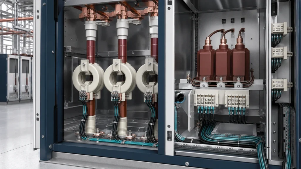
Selecting an instrument transformer requires three distinct data sets: one for metering accuracy, one for protection response, and one for the physical installation environment. The Instrument Transformers selection context provides the relevant product-family starting point. Conflating the data sets is a common source of incorrect procurement — a unit sized for metering may not survive a fault current, and a unit specified only for protection may introduce unacceptable revenue-metering error. Gathering complete, separated data before an RFQ eliminates ambiguous or non-compliant deliveries.
| Dimension | Metering Focus | Protection Focus |
|---|---|---|
| Core saturation intent | Avoids saturation at normal load | Saturates above rated limit current to protect connected equipment |
| Accuracy class driver | Revenue or tariff compliance | Correct relay operation under fault |
| Governing standard scope | IEC 61869-1 general + class-specific parts | IEC 61869-1 general + class-specific parts + IEC 61869-20:2025 for HV safety boundary |
| Failure mode of concern | Ratio or phase error at normal current | Under- or over-reach of protective relay |
| Secondary circuit dependency | Metering panel impedance | Relay burden and CT secondary resistance |
Why Metering and Protection Cores Must Be Specified Independently
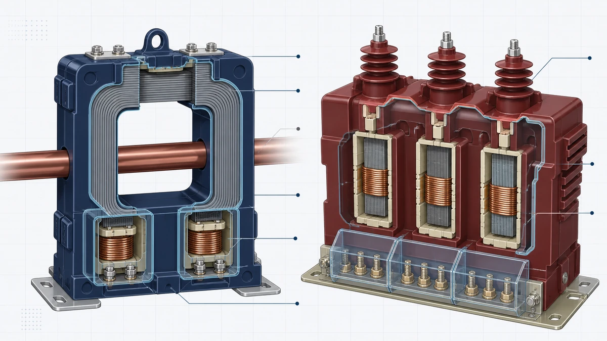
A current transformer core is defined by the trade-off between linear response at normal operating currents and deliberate or controlled saturation at fault currents. Metering cores are wound to maintain tight ratio and phase-angle accuracy across the rated current range, but that precision is irrelevant — and the core design counterproductive — when a fault drives current to many times the rated value. A protection core, by contrast, is characterised by its ability to faithfully reproduce overcurrent multiples up to its accuracy limit factor before saturation clamps the secondary output and protects connected relays and instruments from being driven beyond their thermal or input limits.
Specifying a single core for both duties is possible in principle but requires explicit confirmation from the manufacturer that the same core meets both the metering accuracy class and the protection accuracy limit factor at the expected fault level. Without that confirmation, two separate cores — or a multi-ratio, multi-core design — are the correct procurement approach. Document the intended core assignment for each secondary winding in the RFQ; ambiguity at the specification stage regularly produces field re-wiring or core replacement after commissioning.
Voltage transformers follow the same separation logic. Inductive VTs for metering must hold ratio accuracy within a narrow burden range, while capacitive voltage transformers (CVTs) for protection must reproduce voltage faithfully during transient fault conditions. The two types have different transient response characteristics, and a procurement team that does not record which secondary windings feed revenue meters versus distance relays will inevitably receive a unit optimised for only one of the two.
Application Data to Collect Before Writing an RFQ
Complete instrument transformer selection data starts with the system parameters the transformer must interface with, not with the unit's catalogue numbers. Assemble the following before engaging a supplier:
**System and primary circuit data:** Rated system voltage and highest voltage for equipment (Um), rated frequency, maximum continuous current (for CTs), short-circuit current level and duration, and earthing arrangement. The short-circuit level drives the dynamic and thermal short-circuit current ratings and directly determines whether a standard product is suitable or a project-specific design is required.
**Secondary circuit data:** Measured or calculated burden for each secondary winding, expressed in VA and at the actual power factor of the connected devices. Burden is not the sum of nameplate ratings; it is the impedance of cabling plus the actual relay or metering input impedance at the operating frequency. Under-stating burden pushes the transformer outside its rated accuracy band; over-stating it wastes cost on a larger core than necessary.
**Accuracy requirements by winding:** State the required accuracy class for each winding separately — for example, class 0.2S for revenue metering and class 5P20 for overcurrent protection. The numerical suffix on a protection class (the "20" in 5P20) is the accuracy limit factor, the multiple of rated current to which the accuracy specification applies. Collect the relay manufacturer's stated minimum accuracy limit factor requirement and carry it into the transformer specification.
**Environmental and installation data:** Indoor or outdoor service, ambient temperature range, altitude above sea level (affects dielectric performance), seismic zone if applicable, pollution level, and enclosure or housing requirement. Use the Indoor Instrument Transformers and Outdoor Instrument Transformers contexts to keep the installation environment explicit. For outdoor high-voltage units, the creepage distance required by the pollution level determines the insulator profile and directly affects the physical dimensions of the unit.
IEC 61869-1 and the General Requirements Boundary
IEC 61869-1:2023 establishes the general requirements that apply to all newly manufactured instrument transformers producing either analogue or digital secondary signals, covering measuring, protection, and control applications. It is a foundation standard: every class-specific part of the IEC 61869 series (covering CTs, inductive VTs, CVTs, combined transformers, and electronic instrument transformers) is read in conjunction with 61869-1, not in isolation.
For procurement purposes, the practical boundary of 61869-1 is that it governs type test, routine test, and acceptance test requirements for the transformer as a manufactured product. It does not determine what ratio, accuracy class, or burden a given project requires — those are engineering inputs the buyer must supply. Stating "to IEC 61869-1" in an RFQ without the class-specific part and the project application data yields an ambiguous specification. The correct reference is 61869-1 together with the relevant class-specific part and a fully populated application data sheet.
When reviewing test reports against 61869-1, confirm that routine tests match the specific rated characteristics of the ordered unit, not a similar model from the same family. Voltage withstand and ratio accuracy tests are performed at the rated values stated on the nameplate; a test report for a different voltage class or accuracy class is not transferable.
IEC 61869-20:2025 and the High-Voltage Safety Documentation Boundary
IEC 61869-20:2025 specifies safety requirements for high-voltage instrument transformers and provides a defined boundary for requesting correct project documentation. Its role in the procurement and installation workflow is as a reference for what documentation must exist before installation activities proceed on HV units — it does not replace site-specific switching or safety procedures, which are governed by the asset owner's approved operational procedures and the equipment manufacturer's installation manual.
For an engineering or procurement review, the practical use of 61869-20 is to anchor the documentation request: a high-voltage instrument transformer delivered to site should arrive with transport, storage, and pre-installation inspection documentation that meets the requirements the standard defines. If a delivered unit cannot be traced to compliant documentation, that is a hold point for the project — installation should not proceed until the documentation gap is resolved through the supplier.
The standard also defines the safety boundary relevant to SF₆-insulated and oil-insulated HV units, where handling instructions for insulating media are governed by separate approved procedures. Do not attempt to infer gas pressure limits, oil condition acceptance criteria, or dielectric test voltage levels from the standard alone; request the manufacturer's specific installation and commissioning manual and confirm that the site's approved procedures reference it.
Separating Metering and Protection Requirements in the Data Sheet
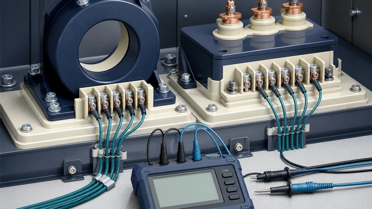
A combined instrument transformer data sheet that does not distinguish metering and protection parameters winding-by-winding will generate clarification requests from every competent supplier. Structure the application data so that each secondary winding has its own row or section, with the accuracy class, burden, and application (revenue metering / tariff metering / overcurrent protection / distance protection / differential protection / supervision) stated explicitly.
For metering windings, the key data points are accuracy class, rated burden, and the current or voltage range over which that accuracy must hold. Class 0.2 and 0.2S differ in their performance at low current multiples — 0.2S extends the accuracy requirement down to 1% of rated current, which matters for installations with highly variable load. Stating the wrong class at the RFQ stage produces a unit that passes factory tests but fails revenue metering approval at commissioning.
For protection windings, the accuracy limit factor and the composite error at that factor are the critical parameters alongside the accuracy class. A 5P20 core maintains composite error below 5% up to 20 times rated current; a 10P10 core maintains 10% composite error up to 10 times. The relay protection engineer must confirm which class and which accuracy limit factor the relay scheme requires before those values enter the transformer specification. Procurement should not back-calculate these from catalogue options; the relay engineer's confirmation should be a traceable document in the project file.
Voltage transformers for protection additionally need the VT factor — the multiple of rated voltage the secondary must withstand without damage or accuracy loss, relevant when the system can develop sustained overvoltages during faults on unearthed or resonant-earthed networks.
Physical and Installation Environment Data
Physical selection data affects supply chain, logistics, and civil or structural design as much as it affects the transformer's electrical ratings. Collect the following and include it in the RFQ:
- **Primary connection type:** Busbar through-type, cable-end, or free-standing post-type for CTs; single-pole or three-pole assembly for VTs. Wrong connection type at delivery is a re-order, not a site modification.
- **Mounting arrangement and primary terminal orientation:** Particularly relevant for GIS-connected units and for CTs installed on cable sealing ends.
- **Outdoor insulation requirements:** Creepage distance class per IEC 60815 for the pollution level at the installation site. Suppliers need the pollution level, not a verbal description of the environment.
- **Seismic requirement:** If the site is in a seismic zone, the horizontal and vertical acceleration levels (typically expressed as a response spectrum) must be stated. Seismic qualification is a distinct type test; not all standard products carry it.
- **Temperature and altitude:** Corrections to rated current apply at altitudes above 1000 m; some manufacturers require project-specific thermal calculations above 2000 m.
- **Space envelope:** Maximum external dimensions or weight constraint for switchgear bays or transformer platforms. This is particularly binding in retrofit projects where the existing civil structure cannot be modified.
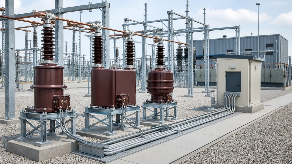
For gas-insulated or oil-insulated HV instrument transformers, the installation requirements extend to transport orientation, minimum storage temperature, and pre-energisation checks defined in the manufacturer's procedures. These are not derivable from the IEC standards alone; they require the model-specific documentation supplied by the manufacturer. Any deviation from the manufacturer's approved pre-installation procedure is a warranty and safety risk that must be escalated to the manufacturer before proceeding.
Commissioning Hold Points and Verification Evidence
Before energisation, the commissioning record for an instrument transformer should include: routine test certificate matched to the unit serial number, ratio and polarity verification performed at site, winding resistance measurement for CT secondary continuity, insulation resistance result, secondary circuit burden measurement, and confirmation that secondary terminals are correctly terminated and not open-circuited (for CTs) or short-circuited (for VTs). An open-circuited CT secondary under primary current is a safety hazard; this check is a commissioning hold point, not a post-energisation observation.
For metering CTs, the as-found secondary burden should be compared to the value used in the accuracy specification. A burden that has grown — due to additional relay inputs, longer cable runs, or corroded connections — moves the CT outside its tested accuracy band. This comparison is evidence the specification team can request as a commissioning deliverable without prescribing any adjustment procedure.
Protection CTs in differential schemes require polarity verification that accounts for the vector group of any power transformer in the protection zone. This verification is a relay engineer's task, but procurement and project teams should confirm it is a stated commissioning requirement in the project documents so it cannot be omitted under schedule pressure.
The IEC 61869-20:2025 safety documentation boundary applies at commissioning as well as at installation: confirm that the commissioned unit's documentation package — including any transport lock removal confirmation and dielectric integrity check for HV units — is complete and in the project file before the energisation hold point is released.
Pre-RFQ Checklist Summary
Use this as a gate before issuing any RFQ or replacement enquiry. Every item left blank is a clarification the supplier will raise, which adds lead time.
**System parameters:** ☐ Rated voltage (Um) ☐ Rated frequency ☐ Short-circuit level and duration ☐ Earthing arrangement ☐ Maximum continuous primary current (CT)
**Per secondary winding:** ☐ Application (metering / protection / control) ☐ Accuracy class ☐ Rated burden (VA, power factor) ☐ Accuracy limit factor (protection windings) ☐ VT factor (VT protection windings on unearthed networks)
**Environmental:** ☐ Indoor / outdoor ☐ Pollution level and required creepage distance ☐ Ambient temperature range ☐ Altitude ☐ Seismic requirement (zone and acceleration)
**Physical:** ☐ Primary connection type ☐ Mounting arrangement ☐ Space envelope / weight limit ☐ Insulation medium (dry, oil, SF₆, solid)
**Standards and documentation:** ☐ IEC 61869-1:2023 general requirements confirmed ☐ Class-specific IEC 61869 part identified ☐ IEC 61869-20:2025 HV safety documentation requirement flagged (if HV) ☐ Manufacturer's installation manual requested
Send the completed data sheet and declared application through Contact Us so the quotation review can remain tied to the metering, protection, and installation requirements actually recorded for the project.
—
FAQ
What is instrument transformer selection data?
Instrument transformer selection data is the complete set of electrical, environmental, and physical parameters needed to specify a current or voltage transformer unambiguously. It includes primary system voltage and current, short-circuit levels, secondary burden and accuracy class for each winding, environmental conditions, and physical installation constraints. Without this full data set, a supplier cannot confirm compliance, and the procured unit may not meet metering or protection requirements at site.
What is the difference between metering and protection accuracy classes under IEC 61869-1?
Metering accuracy classes (0.1, 0.2, 0.2S, 0.5, 0.5S, 1, 3, 5 for CTs; 0.1, 0.2, 0.5, 1, 3 for VTs) define the permissible ratio and phase error across the rated current or voltage range at normal operating conditions. Protection accuracy classes (5P, 10P for CTs; 3P, 6P for VTs) define the permissible composite error at a specified multiple of rated current or voltage — the accuracy limit factor — and are intentionally less precise at normal load. IEC 61869-1:2023 establishes the general framework; the class-specific parts define the detailed test requirements for each class.
What is the role of IEC 61869-20:2025 in an instrument transformer procurement?
IEC 61869-20:2025 specifies safety requirements for high-voltage instrument transformers and establishes the documentation and safety boundary relevant to HV units. In a procurement context, it anchors the list of documents that must accompany a delivered HV instrument transformer — covering transport, storage, pre-installation inspection, and handling of insulating media — before installation activities can safely proceed. It does not replace site-specific switching procedures or the manufacturer's approved installation manual, both of which remain mandatory.
What is secondary burden and why does it affect selection?
Secondary burden is the total impedance presented to the transformer's secondary terminals by the connected devices and cabling, expressed in VA at a stated power factor. A CT or VT maintains its rated accuracy only when the connected burden falls within the rated burden range. If the actual burden exceeds the rated value, the transformer operates outside its tested accuracy band, which causes revenue metering error or may prevent a protection relay from receiving the current or voltage it needs to operate correctly. Burden must be measured or calculated from the actual cable impedance and device input impedance — it cannot be reliably estimated from nameplate ratings alone.
What is the accuracy limit factor for a protection CT?
The accuracy limit factor (ALF) is the multiple of rated primary current up to which the CT maintains its stated protection accuracy class. A designation of 5P20 means the CT holds composite error below 5% at up to 20 times rated current. Above the ALF, the core saturates and the secondary output no longer accurately represents the primary current. The protection relay engineer must confirm the minimum ALF required for each relay function in the scheme; this value must be stated in the transformer specification so the supplied unit can be confirmed to meet it through the routine test certificate.
What is the consequence of leaving a CT secondary open-circuited?
An open-circuited CT secondary winding while primary current flows drives the core into deep saturation and induces a high voltage across the open terminals. This is a safety hazard to personnel and equipment. It is a commissioning hold point: the secondary circuit must be verified as closed and correctly terminated to all connected devices before primary current is applied. Model-specific approved procedures govern the actions for closing, testing, and verifying secondary circuits; these steps should not be improvised on site.

