

Quick Takeaway
- Confirm the project duty and applicable requirements for Instrument Transformers before selection or service work.
- Use recorded inspection and test evidence instead of unsupported assumptions.
- Keep the final acceptance, maintenance, and handover documents with the equipment record.
A CT ratio is a documented electrical parameter that defines the proportional relationship between primary current and secondary current in a current transformer, but reading that ratio in isolation does not tell you whether the CT is suitable for your metering circuit, your protection scheme, or the fault levels at your installation site. The ratio must be interpreted alongside burden, accuracy class, application type, and project-specific evidence before any procurement or replacement decision can be made. This article explains what the ratio communicates, what it leaves open, and what evidence you need to collect before issuing an RFQ or approving a substitution in the Instrument Transformers context.
What the CT Ratio Physically Represents
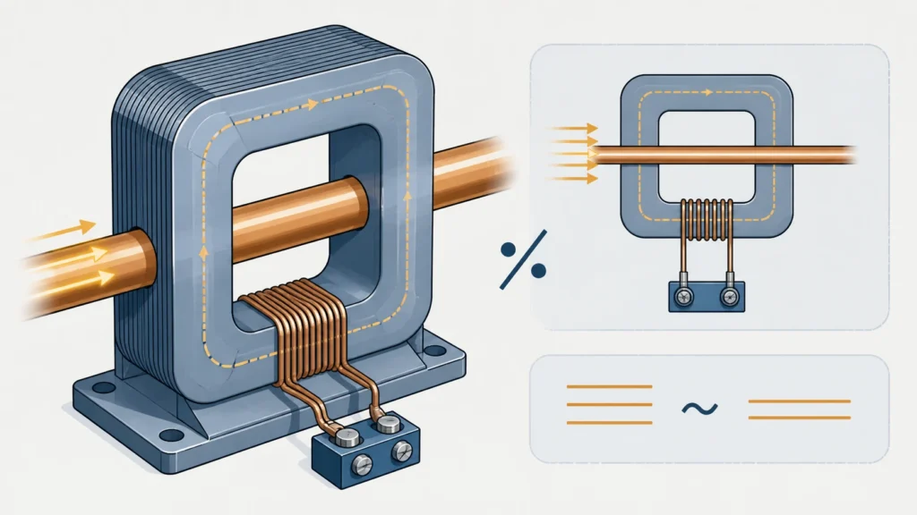
A current transformer steps down a high primary current to a standardized, measurable secondary current. The CT ratio, expressed as primary current to secondary current (for example, 400/5 or 800/1), describes this proportional transformation under rated conditions. A 600/5 CT is wound so that when 600 A flows in the primary conductor, approximately 5 A flows in the secondary winding and through the connected metering or protection instrument.
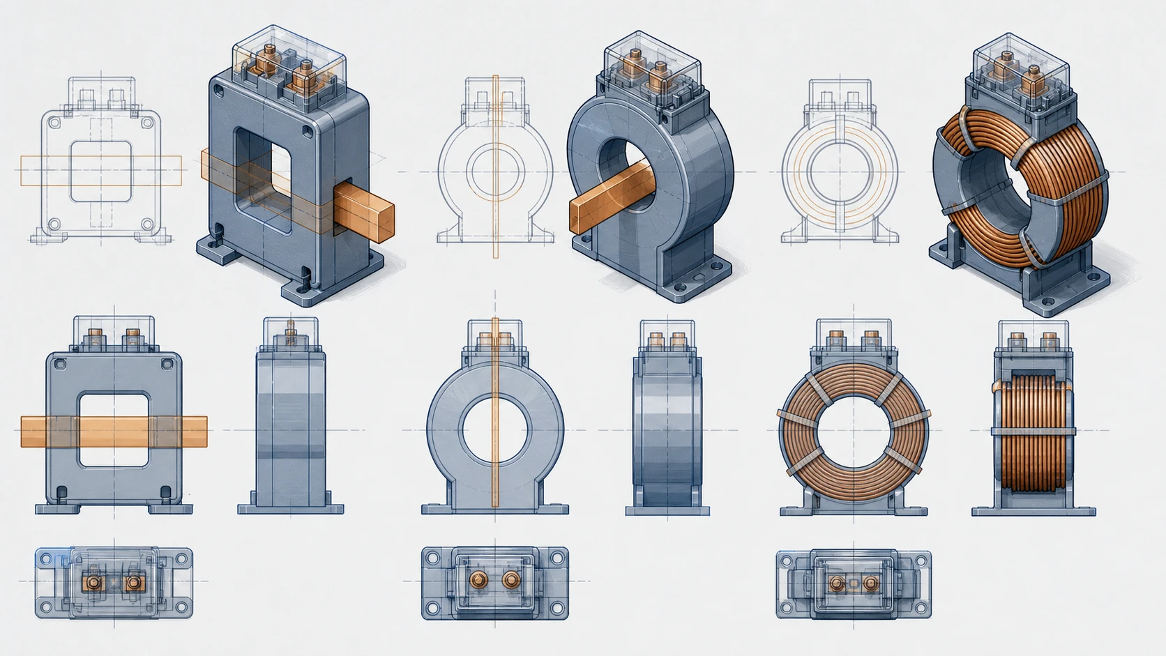
The ratio is a consequence of the turns ratio between primary and secondary windings, adjusted for magnetizing current losses. In a window-type CT with a single primary pass-through, the turns ratio equals the number of secondary turns. In a wound-primary CT, both primary and secondary turn counts determine the ratio. The key point is that the stamped ratio describes rated-condition behavior. It does not describe behavior at every operating point, under every burden, or at fault-current magnitudes far above the rated primary value.
What the Ratio Tells You
The CT ratio communicates several concrete facts that are useful at the consideration stage:
The nominal operating range is bounded by the rated primary current. A 200/5 CT is designed for circuits where normal load current falls within a range that makes 200 A a reasonable full-scale value. If your expected load current is 80 A, a 200/5 CT will operate in the lower portion of its range, which may or may not be acceptable depending on accuracy class requirements at that operating point.
The secondary output magnitude is fixed by convention. Most instrument transformers deliver either 5 A or 1 A at rated primary current. The ratio tells you which secondary standard applies, which directly determines the compatibility of connected instruments, relay inputs, and wiring burden calculations.
The ratio also implies a voltage and energy capacity relationship. A higher-ratio CT on the same core must develop more voltage to drive secondary current through a given burden. This relationship links ratio selection to burden limits, but the ratio alone does not quantify the burden capacity.
What the Ratio Does Not Decide
This is where misreading a ratio leads to specification errors, failed commissioning, or degraded measurement accuracy.
**Accuracy class is independent of the ratio.** Two CTs can share the same 400/5 ratio while one meets IEC 61869-2 class 0.2S for revenue metering and the other meets class 5P20 for protection. The ratio does not encode accuracy class. IEC 61869-2 specifies additional requirements for current transformers, including accuracy class designations, composite error limits, and instrument security factor, all of which sit alongside the ratio as separate, mandatory specification parameters.
**Burden capacity is not implied.** A 400/5 CT rated at 15 VA behaves differently from a 400/5 CT rated at 30 VA when connected to the same secondary circuit. The ratio is the same; the ability to maintain accuracy under load is not.
**Saturation behavior under fault conditions is ratio-adjacent but not ratio-determined.** A protection CT must reproduce current waveforms faithfully up to a defined multiple of rated current, expressed as the accuracy limit factor (ALF). A 400/5 CT with 5P20 accuracy must maintain its class 5P accuracy up to 20 times rated current, meaning up to 8,000 A on the primary side. The ratio tells you the base; the ALF tells you the ceiling. Omitting the ALF when specifying a protection CT is a common procurement error.
**Application type, metering or protection, is a design decision the ratio cannot make.** ABB describes indoor current transformers for both metering and protection applications, and the same catalog may list identical ratios across different product lines distinguished by accuracy class and saturation characteristics. A procurement team that matches only on ratio risks ordering a metering-class CT for a protection application, or vice versa. The system context belongs in the wider MV Switching Equipment record.
| Parameter | Encoded in the CT ratio? | Where to find it |
|---|---|---|
| Nominal primary current | Yes | Nameplate, datasheet |
| Secondary current standard (1 A or 5 A) | Yes | Nameplate, datasheet |
| Accuracy class | No | Datasheet, IEC 61869-2 designation |
| Rated burden (VA) | No | Datasheet |
| Accuracy limit factor (ALF) | No | Datasheet, protection coordination study |
| Insulation level / voltage class | No | Datasheet, system voltage study |
| Thermal short-time current rating | No | Datasheet, fault study |
| Mounting and dimensional envelope | No | Outline drawing |
The Evidence You Need Before the Ratio Becomes Useful
Reading a CT ratio is not a decision; it is the start of an evidence-gathering process. Use the instrument transformer selection-data checklist as a baseline before the following inputs are assembled.
**System single-line diagram and load study.** The expected load current range determines whether the ratio places normal operating current in a measurement-accurate zone. Operating consistently below 10–20 percent of the rated primary value degrades metering accuracy in most accuracy classes.
**Fault-level study.** Maximum prospective fault current at the CT location determines whether a protection-class CT can reproduce fault waveforms without saturating prematurely. The ratio sets the base; the fault study determines whether the ALF is adequate.
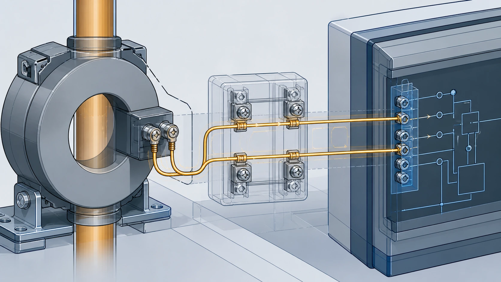
**Connected burden inventory.** Every device on the secondary circuit, relay coil, meter input, lead resistance, and terminal contact resistance, contributes to burden. The total burden must fall within the CT's rated burden for the specified accuracy class to hold.
**Application designation.** The engineering team must state whether the CT serves metering, protection, or a combined function. IEC 61869-2 draws a clear line between metering accuracy classes (which prioritize precision at rated current) and protection accuracy classes (which prioritize faithful reproduction at high multiples of rated current). A single ratio can appear in both families; the application determines which accuracy class applies.
**Voltage class and insulation coordination.** The ratio says nothing about whether the CT is rated for a 12 kV, 24 kV, or 36 kV system. Insulation level must be verified against system voltage independently.
Reading a Nameplate: Ratio in Context
A CT nameplate or datasheet bundles the ratio with the parameters that give it meaning. A typical IEC-compliant designation might read:
`400/5 A, Class 0.5, 15 VA, 50 Hz`
Each element qualifies the others. The 400/5 ratio is valid at class 0.5 accuracy only when the connected burden does not exceed 15 VA and the system frequency is 50 Hz. Change any one parameter and the stated accuracy class may no longer apply.
For protection CTs, the designation extends to include the accuracy limit factor:
`400/5 A, 5P20, 30 VA, 50 Hz`
Here, 5P20 means the composite error stays within 5 percent up to 20 times rated current. The ratio sets the primary reference; the 5P20 class sets the dynamic range. Procurement documents that omit the accuracy class or ALF and specify only "400/5 CT" leave the supplier to assume an application, which introduces substitution risk.
Multi-Ratio and Tap Configurations
Some current transformers offer multiple ratios through tapped secondary windings. A CT might be listed as 200-400-600/5, meaning the secondary can be reconnected to provide three discrete ratios from the same core and housing.
Multi-ratio CTs add flexibility but also add a verification step. The accuracy class and burden rating may differ across taps. A CT that meets class 0.5 at the 600/5 tap may only meet class 1.0 at the 200/5 tap because fewer active secondary turns change the magnetizing current proportion. Confirming accuracy class at the specific tap in use, not just at the highest ratio, is a required evidence step.
Common Misinterpretations That Create Procurement Risk
**Assuming ratio equivalence means interchangeability.** Two 800/1 CTs from different manufacturers or product lines are not interchangeable unless accuracy class, burden, ALF, insulation level, thermal ratings, and dimensional envelope all match. The ratio is necessary but nowhere near sufficient for a substitution decision.
**Confusing rated primary current with maximum continuous current.** The rated primary current in the ratio is the value for which the stated accuracy class is specified. Some CTs may carry 120 percent of rated current continuously without thermal damage, but that extended range is specified separately. Operating at 150 percent of rated primary current because the CT "hasn't tripped anything" does not mean accuracy is maintained.
**Ignoring extended current range for metering.** IEC 61869-2 defines extended current ratings for metering CTs, such as class 0.2S, which require accuracy down to 1 percent of rated current. A 1000/5 CT in class 0.2S must be accurate at 10 A primary. A 1000/5 CT in class 0.5 does not carry that same low-end obligation. The ratio is identical; the metering capability at light load is not.

A Practical Review Sequence Before RFQ or Replacement
Rather than treating ratio selection as a standalone task, treat it as one checkpoint in a structured evidence review. The following sequence applies whether you are specifying a new CT or approving a replacement for an installed unit.
1. Confirm the application type: metering, protection, or combined.
2. Record the expected load current range and verify that the candidate ratio places normal operation within the accuracy-class-valid zone.
3. Record the maximum prospective fault current and verify that the candidate ALF (for protection CTs) provides adequate headroom.
4. Sum the connected burden, including lead resistance, and verify it falls within the CT's rated burden at the intended ratio and tap.
5. Confirm the voltage class and insulation level match the system voltage.
6. Confirm the thermal short-time current rating meets or exceeds the fault-level study results.
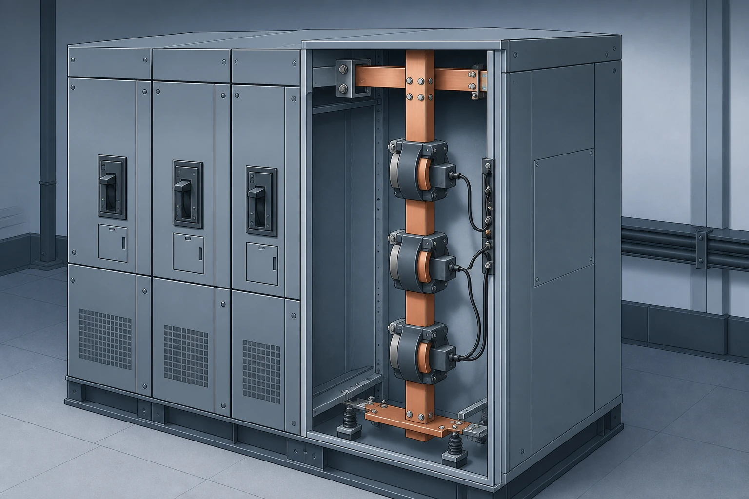
7. Confirm the physical dimensions and mounting arrangement fit the switchgear, panel, or busbar configuration.
8. Document all of the above in the specification or replacement justification, including the mounting interface in the relevant MV switchgear components record. A ratio alone is not a specification.
This guide is not an engineering approval or a substitute for a project-specific design review. A qualified engineering authority must confirm the model-specific configuration, applicable documentation, and manufacturer procedure before installation, connection, commissioning testing, or demagnetization. Those requirements depend on the project and product scope.
FAQ
What is a CT ratio?
A CT ratio is the proportional relationship between the rated primary current and the rated secondary current of a current transformer, expressed as a pair such as 400/5 or 800/1. It defines the scale factor that connected instruments use to infer primary system current from the smaller, safer secondary current.
What is the difference between a metering CT ratio and a protection CT ratio?
The ratio itself can be numerically identical. The difference lies in the accuracy class applied to that ratio. A metering CT is optimized for precision at and near rated current, while a protection CT is optimized for faithful waveform reproduction at high multiples of rated current during faults. IEC 61869-2 defines these as separate accuracy class families. The ratio does not indicate which family applies; the accuracy class designation does.
What is the risk of specifying only the CT ratio on a purchase order?
Specifying only the ratio leaves the accuracy class, burden rating, accuracy limit factor, voltage class, frequency, and thermal ratings undefined. The supplier must either assume these values or request clarification, both of which introduce delay or substitution risk. A complete CT specification includes at minimum the ratio, accuracy class, rated burden, system voltage, frequency, and application type.
What is the relationship between CT ratio and burden?
The CT ratio determines the secondary current magnitude, and the burden is the total impedance of the secondary circuit that this current must flow through. A higher burden requires the CT to develop more voltage across the secondary, which increases the magnetizing current and can degrade accuracy. The ratio and burden must be evaluated together; neither is meaningful in isolation for accuracy verification.

