

Quick Takeaway
- Confirm the project duty and applicable requirements for Load Break Switches before selection or service work.
- Use recorded inspection and test evidence instead of unsupported assumptions.
- Keep the final acceptance, maintenance, and handover documents with the equipment record.
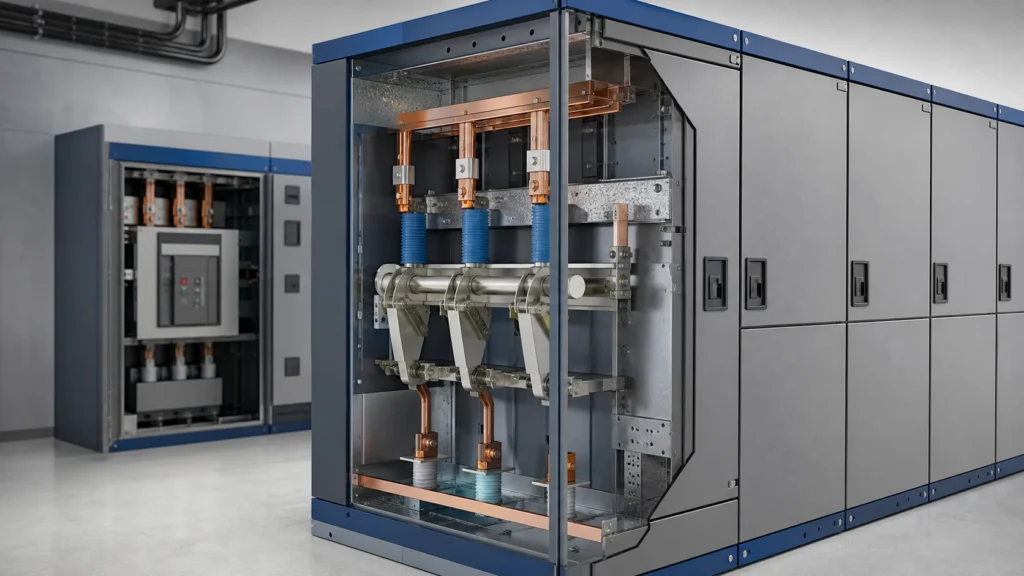
A medium voltage load break switch is a switching device designed to make, carry, and interrupt load currents at medium-voltage levels — but it is not designed to interrupt fault currents. That single functional boundary defines its role in a power system and every procurement decision that follows from it. Understanding what a load break switch does, what it does not do, and what evidence you need before specifying one prevents costly misapplication and avoids RFQ confusion with circuit breakers or disconnectors.
Functional Role and What It Is Not
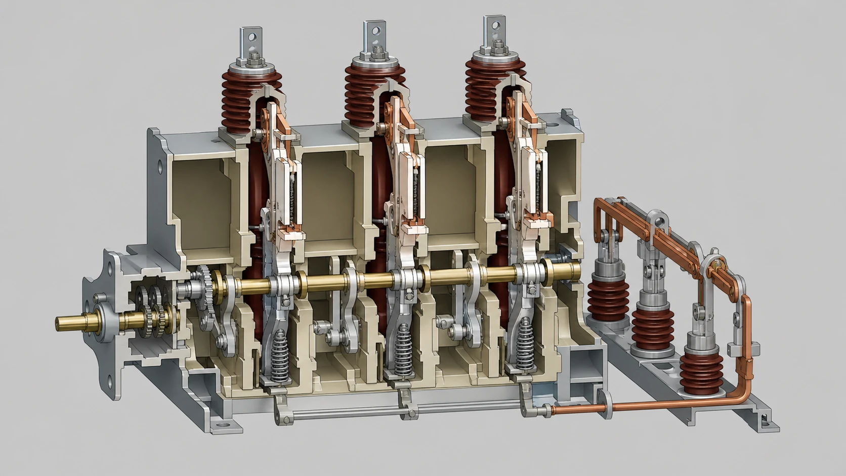
A load break switch occupies a specific middle position in the switching-device hierarchy. A disconnector (isolator) provides visible isolation but must never be opened under load. A circuit breaker can interrupt both load currents and fault currents. A load break switch sits between the two: it can safely interrupt normal load currents and some overload currents, but it relies on upstream or downstream protective devices for fault-current interruption.
This is not an interchangeability statement. Equipment catalogs sometimes describe a product as a "switch-disconnector," combining load-break capability with the isolation function. The Schneider Electric PM6 catalog, for example, describes a medium-voltage switch-disconnector range with documented configurations that serve both roles in a single device. That combined designation does not make the device a circuit breaker, and it does not mean every load break switch also qualifies as a disconnector. The procurement task is to verify the specific ratings and standards compliance of the device you are evaluating — not to assume equivalence from a category label.
| Attribute | Disconnector | Load Break Switch | Circuit Breaker |
|---|---|---|---|
| Opens under load | No | Yes | Yes |
| Interrupts fault current | No | No | Yes |
| Provides visible isolation | Yes | Some designs | Typically no |
| Typical role | Maintenance isolation | Operational switching, load transfer | Protection, fault clearing |
| Requires upstream protection for faults | N/A (not switched under load) | Yes | No (is the protective device) |
Keep this table available during specification review. If a vendor proposal blurs the boundary between any two columns, that is an evidence gap to resolve before award.
The Interruption Mechanism and Why It Matters for Selection
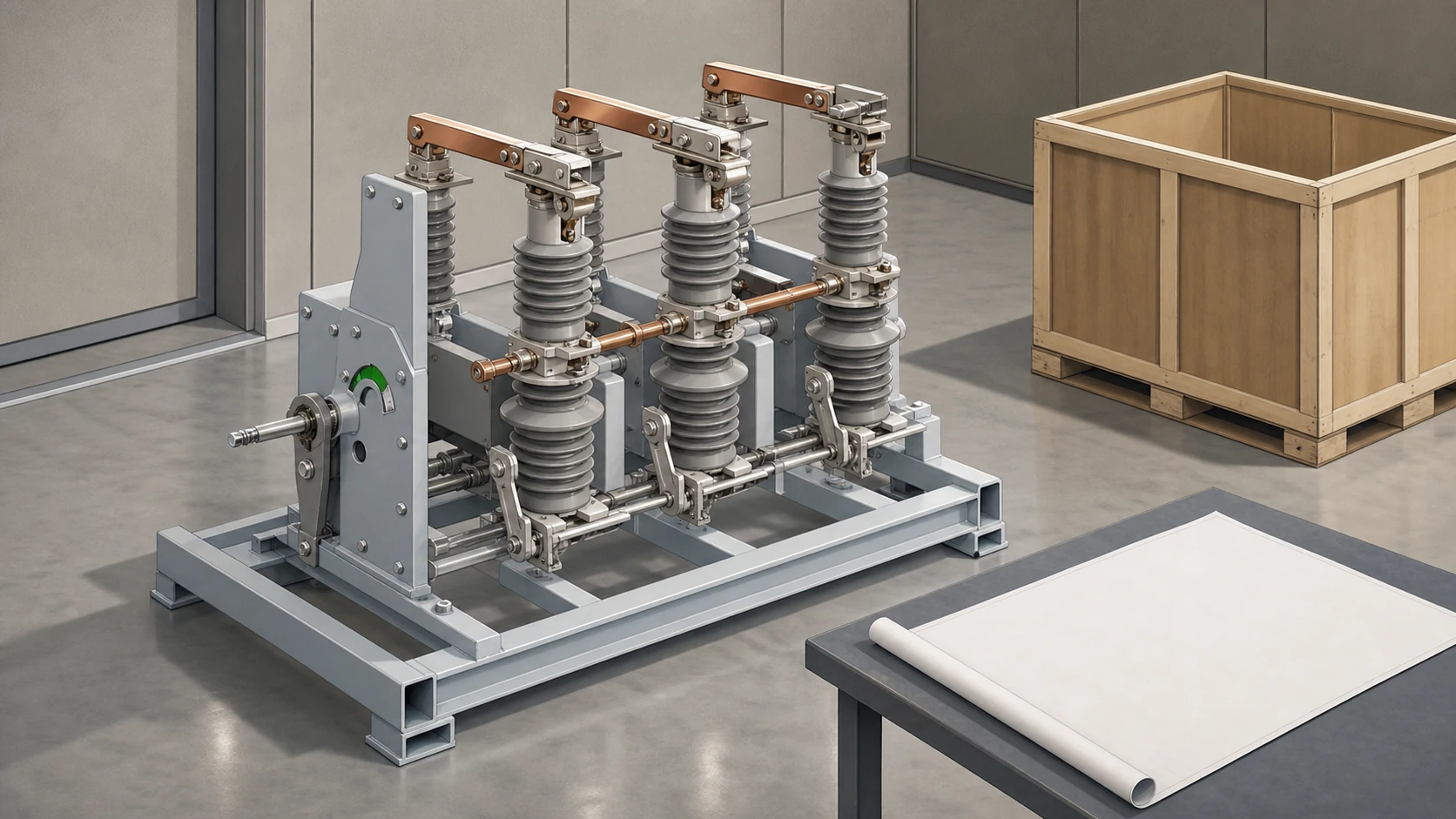
The way a load break switch extinguishes the arc during a load-current interruption directly affects its voltage rating, its service-life expectancy, and its maintenance profile. Common medium-voltage interruption technologies include:
- **Gas-insulated (SF₆ or alternatives).** The arc is extinguished in a sealed gas compartment. These units tend to be compact, have long maintenance intervals, and are favored in indoor substations or space-constrained switchgear lineups. Environmental and regulatory pressure on SF₆ is driving some manufacturers toward alternative gases; confirm the specific gas and any end-of-life obligations before procurement.
- **Vacuum.** The arc is drawn and extinguished in a vacuum interrupter bottle. Vacuum load break switches share technology lineage with vacuum circuit breakers but are rated only for load-current interruption. Do not assume a vacuum load break switch can be field-upgraded to circuit-breaker duty.
- **Air or spring-operated with arc chutes.** Older or specialized designs use air as the insulating and arc-quenching medium. These may require more frequent inspection of arc-chute condition. The Schneider Electric MotorSeT, identified in its instruction bulletin as a medium-voltage load break interrupter switch for motor-control equipment, represents a product-role example in which the switching component is integrated into a specific application assembly rather than offered as a standalone panel device.
The interruption medium is not a quality ranking. It is a design parameter that must match your installation environment, your maintenance capability, and your switchgear enclosure. A gas-insulated unit installed where the operator cannot manage sealed-gas servicing creates a long-term cost problem, regardless of its technical elegance.
Standards, Ratings, and the Evidence You Must Verify
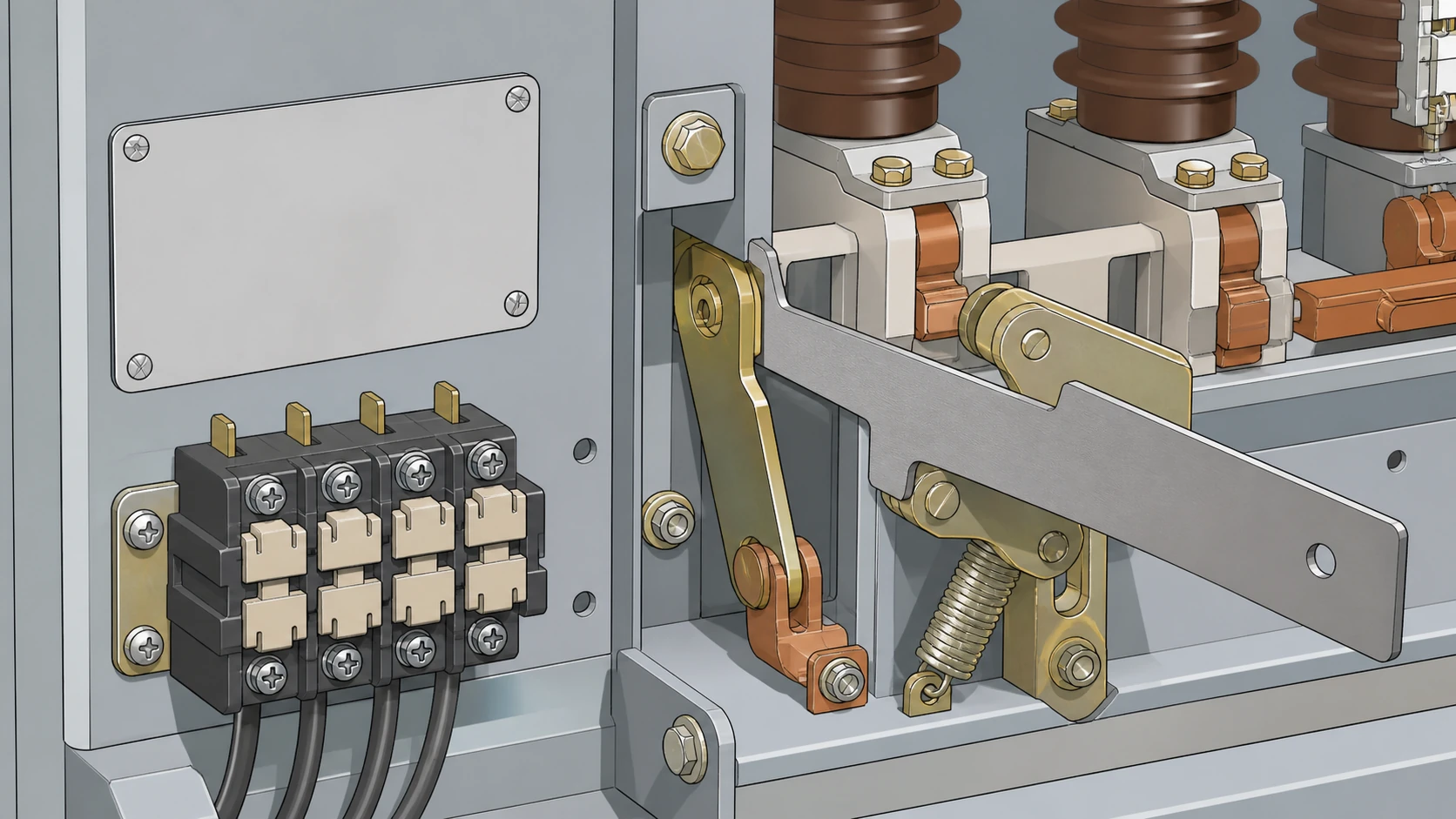
Medium-voltage load break switches are covered by IEC 62271-103 (high-voltage switches above 1 kV) and, in North American practice, by IEEE C37.30-series standards. These standards define the test sequences that validate a device's load-breaking, load-making, and short-time withstand ratings.
Three ratings carry the most procurement significance:
1. **Rated voltage and insulation level.** The maximum system voltage the device is designed for, plus the lightning-impulse and power-frequency withstand levels. A 12 kV-rated switch is not automatically suitable for every system operating below 12 kV; the insulation coordination must match the site's exposure category.
2. **Rated normal current.** The continuous current the switch can carry without exceeding temperature-rise limits. Confirm the test standard and ambient-temperature assumptions; a switch tested at 40 °C ambient may derate in a 55 °C enclosure.
3. **Rated short-time withstand current and duration.** The fault current the switch can carry (without interrupting it) for a specified duration, typically 1 or 3 seconds. This value must coordinate with the system's prospective fault current and the upstream breaker's clearing time. If the prospective fault current at the installation point exceeds the switch's short-time withstand, the switch is not suitable — regardless of its load-break rating.
Do not accept a product datasheet as proof of standards compliance. Request the specific test-report reference or type-test certificate number. If the vendor cannot provide it, that is a material gap in your evaluation.
Configuration and Interface Dependencies
A load break switch does not exist in isolation. Its value in a procurement decision depends on how it interfaces with the rest of the switchgear assembly. Key configuration questions include:
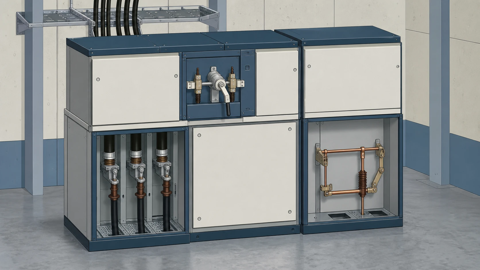
**Mounting and enclosure integration.** Is the switch supplied as a standalone unit for panel mounting, or is it factory-integrated into a specific switchgear lineup? The PM6 switch-disconnector range documented by Schneider Electric, for instance, includes multiple documented configurations — but the suitability of any one configuration depends on the specific enclosure, busbar arrangement, and cable-termination geometry at your site. A configuration that is cataloged is not automatically a configuration that fits your layout.
**Operating mechanism.** Load break switches may be manually operated, motor-operated, or equipped for remote or automated switching via SCADA integration. Motor-operated variants require an auxiliary power supply and control-circuit interface. If your site needs automated load transfer or remote switching, the operating-mechanism specification is as important as the electrical ratings.
**Earthing (grounding) provisions.** Many load break switch assemblies include an integral earthing switch that allows the downstream circuit to be grounded after the load break switch is opened. Confirm whether the earthing switch is included, whether it is rated for making onto a fault (a "fault-make" earthing switch per IEC 62271-102), and whether its mechanical interlocking sequence matches your safety and isolation procedures.
**Auxiliary contacts and position indication.** Procurement specifications should define the number and type of auxiliary contacts needed for signaling switch position to protection relays, SCADA, or local indication. A missing auxiliary-contact requirement discovered after delivery creates a retrofit problem.
Selection and Verification Workflow for Procurement
Merge your technical evaluation and procurement qualification into a single workflow. Treating them as separate processes leads to specifications that are technically correct but commercially incomplete, or commercially competitive but technically ambiguous.
**Step 1 — Establish site electrical parameters.** Collect the system voltage, prospective fault level, maximum continuous load current, ambient temperature, altitude, and pollution degree at the installation point. Each of these parameters directly constrains the switch selection.
**Step 2 — Define the operational role.** Determine whether the switch will be used for routine load switching, load transfer between sources, isolation for maintenance, motor-control switching, or a combination. The Schneider Electric MotorSeT instruction bulletin illustrates how a load break interrupter switch can serve as a switching component within motor-control equipment — a role that imposes duty-cycle and coordination requirements beyond simple load transfer. Your operational role definition shapes both the duty-class requirement and the mechanical-endurance specification.
**Step 3 — Confirm the interruption medium and maintenance model.** Match the interruption technology to your site's maintenance capability and any environmental or regulatory constraints. Document this decision explicitly in the RFQ so that vendors respond with a compatible technology rather than substituting their standard offering.
**Step 4 — Specify standards and evidence requirements.** State the required IEC or IEEE standard edition, the test-report or type-test certificate expectation, and any additional qualification requirements such as seismic withstand or internal-arc classification. Ambiguity here invites non-comparable bids.
**Step 5 — Define interface and accessory requirements.** List the operating mechanism type, auxiliary power supply parameters, auxiliary contact count and type, earthing switch requirement, mechanical interlocking scheme, and any SCADA protocol requirements. Include the enclosure or switchgear designation if the switch must integrate into existing equipment.
**Step 6 — Request coordinated documentation.** The RFQ should require the vendor to supply, at minimum: a rated characteristics table traceable to the applicable standard, a dimensioned installation drawing, a wiring diagram for the operating mechanism and auxiliary contacts, and the type-test certificate or test-report reference. Missing documentation is a disqualification criterion, not a post-award punchlist item.
Installation Risks and Failure Modes Relevant to Specification
Procurement decisions made without awareness of downstream installation and failure risks tend to optimize for price alone. These risks should inform your specification, not your installation procedure — model-specific approved procedures govern all live installation, switching, and maintenance actions.
**Insufficient short-time withstand rating.** If the system fault level grows (due to utility upgrades, parallel transformer additions, or plant expansion) and exceeds the switch's rated short-time withstand current, the switch becomes a safety liability. Specify based on the projected fault level, not only the present one, and document the design margin in the procurement file.
**Interlock failures.** Load break switches integrated with earthing switches depend on mechanical or electrical interlocking to prevent unsafe switching sequences. A specification that omits the interlocking-scheme requirement leaves the interlock design to the vendor's default, which may not match your site's operating and safety procedures.
**Environmental degradation.** Switches installed in high-humidity, high-pollution, or corrosive environments may experience insulation degradation or mechanism corrosion faster than the manufacturer's standard service-life projection. Confirm that the pollution degree and environmental ratings in the product documentation match the actual site conditions.
**Incorrect duty-class application.** A switch specified for infrequent manual load transfer but operated in a frequent automated duty cycle will reach its mechanical-endurance limit prematurely. The duty class (E1, E2, or E3 per IEC 62271-103, or the equivalent in the applicable standard) must match the intended operational profile.
Building the RFQ Data Package
Before issuing an RFQ for a medium voltage load break switch, assemble the following data into a single technical specification attachment. Every item corresponds to a decision made in the selection workflow above.
- System voltage and rated voltage requirement
- Rated normal current requirement
- Prospective fault current at the installation point and required short-time withstand current and duration
- Lightning-impulse and power-frequency withstand voltage levels
- Insulation medium preference or constraint, with justification
- Interruption medium preference or constraint, with justification
- Operating mechanism type and auxiliary power supply parameters
- Duty class (E1, E2, or E3) and expected number of operating cycles per year
- Earthing switch requirement, including fault-make rating if applicable
- Mechanical interlocking scheme description
- Auxiliary contact schedule (quantity, type, function)
- SCADA or remote-control interface requirements
- Environmental conditions: ambient temperature range, altitude, humidity, pollution degree
- Applicable standards edition and required evidence (type-test certificate, routine-test protocol)
- Enclosure or switchgear integration constraints, including dimensioned space envelope
- Spare-parts and long-term support expectations
Issuing an RFQ without this data package does not save time. It shifts the specification effort to the bid-clarification phase, where it costs more and introduces ambiguity into the commercial comparison.
FAQ
What is the difference between a load break switch and a circuit breaker?
A load break switch can interrupt normal load currents but cannot interrupt fault currents. A circuit breaker can do both. This means a load break switch always requires a separate upstream or downstream protective device — typically a fuse or a circuit breaker — to handle short-circuit faults. The two devices are not interchangeable, and specifying one where the other is required creates a safety and coordination problem.
What is the role of a load break switch in motor-control applications?
In motor-control equipment, a load break switch serves as the switching component that connects and disconnects the motor circuit under normal load conditions. The Schneider Electric MotorSeT instruction bulletin describes this role specifically, identifying the device as a medium-voltage load break interrupter switch integrated into motor-control assemblies. The duty-cycle and coordination requirements in motor-control service differ from simple load-transfer applications, so the switch specification must reflect the motor-starting and stopping frequency.
What is a switch-disconnector, and is it the same as a load break switch?
A switch-disconnector combines load-break capability with the isolation function of a disconnector in a single device. The Schneider Electric PM6 catalog documents a medium-voltage switch-disconnector range with multiple configurations. Not every load break switch qualifies as a switch-disconnector, and not every switch-disconnector is rated identically across all configurations. Verify the specific device's rated characteristics and standards compliance rather than relying on the category label.
What is the most important rating to verify before issuing an RFQ?
The rated short-time withstand current and duration. This rating determines whether the switch can survive a fault on the system without damage while the upstream protective device clears the fault. If this rating is insufficient for the prospective fault level at the installation point, the switch is unsuitable regardless of its load-break performance. Specify based on the projected fault level, accounting for planned system growth, not only the present calculated value.
What is the significance of the duty class (E1, E2, E3) in procurement?
The IEC 62271-103 duty classes — E1 (infrequent operation), E2 (frequent operation), and E3 (very frequent operation) — define the mechanical and electrical endurance the switch is tested and warranted for. Specifying E1 for a switch that will be automated for daily load transfers leads to premature mechanical wear and early failure. Match the duty class to the actual operational profile, and document the expected annual operating-cycle count in the RFQ.
What is the risk of omitting interlocking requirements from the specification?
Without a defined interlocking scheme, the vendor supplies the default mechanical arrangement, which may not prevent the unsafe switching sequences specific to your site's operating procedures. For example, a load break switch with an integral earthing switch requires interlocking that prevents closing the earthing switch while the main switch is closed, and prevents closing the main switch while the earthing switch is closed. If the supplied interlocking does not match your safety requirements, the gap is discovered during commissioning — the most expensive point to resolve it.

