

Quick Takeaway
- Confirm the project duty and applicable requirements for Conductive Components before selection or service work.
- Use recorded inspection and test evidence instead of unsupported assumptions.
- Keep the final acceptance, maintenance, and handover documents with the equipment record.
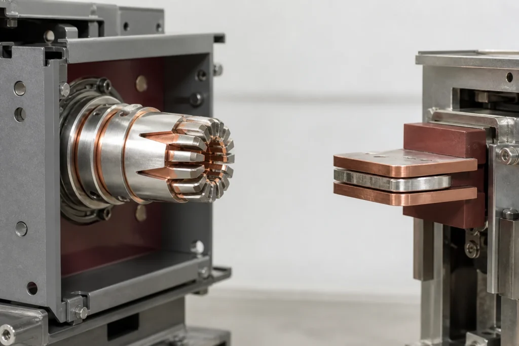
Flat contacts and tulip contacts are geometrically distinct mating systems that perform the same electrical function — carrying rated current through a separable interface — but they are not interchangeable and they are not selected independently of the switchgear that houses them. The contact geometry dictates the mating mechanism, the current-transfer path, the wear profile, and the fixed-side interface that must already exist in the panel or circuit-breaker truck. Any replacement or procurement decision begins not with a preference between the two types but with the OEM documentation for the exact circuit-breaker model and panel design, because the mating contact, the withdrawable assembly, and the panel's fixed tulip or flat bus interface form one validated system. The Vacuum Circuit Breakers category provides the wider equipment context.
| Decision dimension | Flat (clamp) contacts | Tulip contacts |
|---|---|---|
| Mating geometry | Parallel clamping surfaces press against a flat or slightly profiled bus blade | Multiple spring-loaded fingers surround a cylindrical or tapered spigot |
| Current-transfer path | Distributed across two planar faces; contact area depends on clamping force and surface condition | Distributed across an array of finger-to-spigot line contacts; redundancy increases with finger count |
| Typical fixed-side interface | Flat bus bar or blade termination on the panel side | Fixed tulip receptacle or spigot mounted in the panel's stationary portion |
| Alignment sensitivity | Moderate; lateral misalignment reduces overlap area | Lower per-finger but cumulative; axial alignment is critical for uniform finger engagement |
| Wear indicator | Surface erosion, pitting, or discoloration on clamping faces | Finger spring fatigue, uneven finger wear, or spigot scoring |
| OEM specificity | Model-specific; ABB identifies clamp contacts as one option for certain withdrawable circuit-breaker assemblies | Model-specific; ABB documents isolating tulips in specific panel designs and withdrawable assemblies |

Why Contact Geometry Is a System-Level Decision, Not a Component-Level Preference
A contact is half of a joint. A flat contact requires a flat mating surface on the fixed side; a tulip contact requires a compatible spigot or receptacle. Choosing one type without confirming the fixed-side geometry produces a mechanical mismatch that either prevents insertion of the withdrawable element or creates a high-resistance interface that degrades under load. This is not a theoretical risk — it is the reason OEMs document contact nomenclature and mating geometry as model-specific information.
ABB's HD4-DR circuit-breaker manual addendum identifies tulip and clamp contact options as components tied to a specific withdrawable circuit-breaker assembly. The takeaway is precise: the contact type is a function of the breaker model, not a field decision. A procurement engineer reviewing an RFQ should treat the OEM's contact designation as a fixed constraint, not as one option among several.
The same principle applies on the panel side. ABB's ZS8.4 panel design and equipment manual documents isolating tulips and their relationship to the withdrawable component in a specific panel design. The fixed tulip in that panel exists because the withdrawable element was designed to mate with it. Substituting a flat-contact breaker into a panel designed for tulip engagement, or vice versa, requires not just a different contact but a different fixed-side interface — a change that affects the panel's type-test validation.
Functional Distinction: How Each Geometry Transfers Current
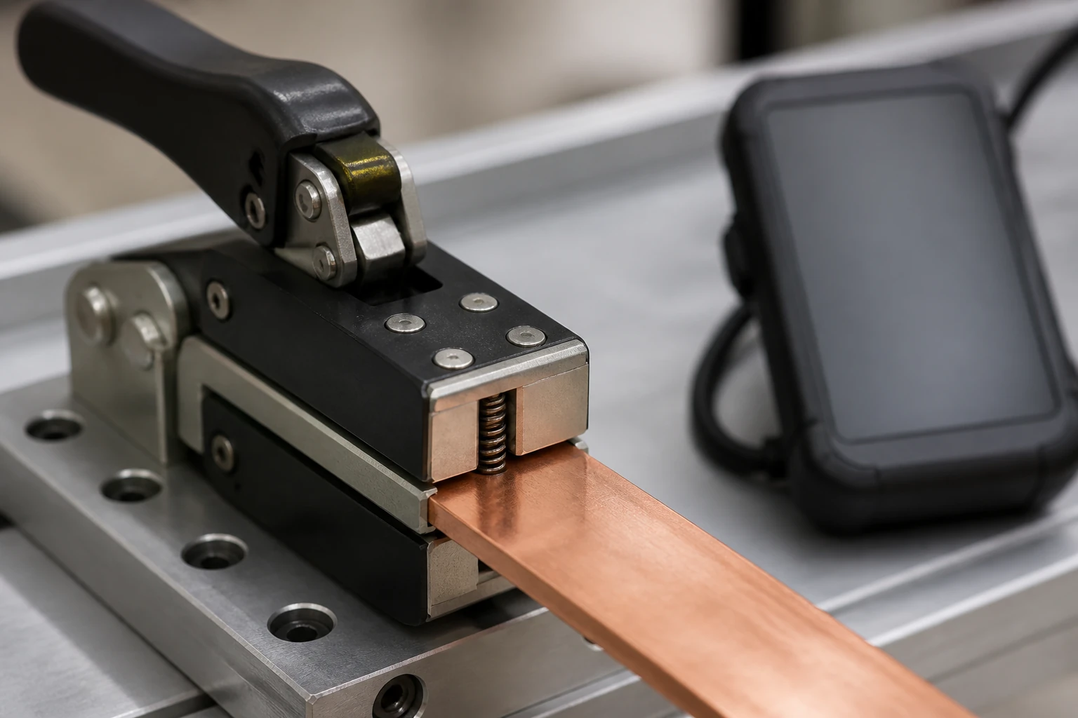
Flat contacts transfer current across two broad, parallel surfaces pressed together by spring force or mechanical clamping. The real contact area is smaller than the apparent area because surface roughness limits metal-to-metal touch points to microscopic asperities. Current crowds through those asperities, and the resulting constriction resistance is sensitive to clamping force, surface finish, and contamination. A flat contact that loses clamping force — through spring relaxation, mechanical wear, or foreign material on the faces — experiences rising contact resistance and localized heating.
Tulip contacts distribute current across an array of spring-loaded fingers, each making independent line contact with a central spigot. The geometry provides built-in redundancy: if one finger loses pressure or develops surface degradation, the remaining fingers continue to carry current. However, the total contact force is the sum of individual finger spring forces, and spring fatigue across the array degrades the entire joint. Tulip contacts are also sensitive to spigot condition; scoring, pitting, or diameter reduction on the spigot changes the engagement geometry for every finger simultaneously.
Both systems rely on adequate contact pressure to maintain low resistance. Neither geometry is inherently superior; each is optimized for a specific mating interface and a specific set of mechanical tolerances defined by the OEM.
Interface and Configuration Dependencies
The mating interface is the critical variable that most procurement and replacement decisions overlook. A flat contact mates with a flat bus blade whose width, thickness, and edge profile must fall within the contact's design envelope. A tulip contact mates with a spigot whose diameter and taper must match the finger array's engagement range. These dimensions are not standardized across manufacturers or even across product lines from a single manufacturer.
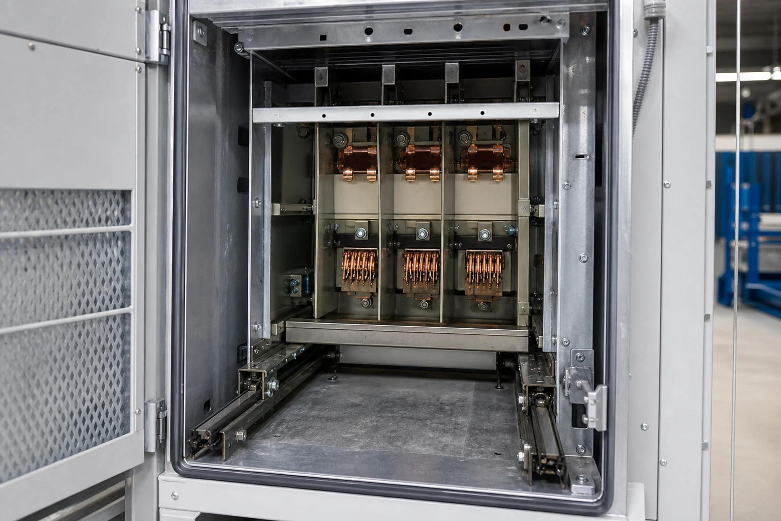
Configuration dependencies extend beyond geometry. The withdrawable circuit-breaker assembly's racking mechanism, its travel distance, and its engagement sequence are all designed around the contact type. A breaker with tulip primary contacts racks into a panel whose fixed tulips or spigots are positioned to align at the test and service positions. Changing the contact type without changing the racking geometry and the fixed-side hardware is not a supported modification.
For procurement, this means the bill of materials for a contact replacement must reference the exact breaker model, the exact panel model, and the exact contact part number. Generic descriptions like "tulip contact for medium-voltage breaker" are insufficient. The ABB documentation referenced here demonstrates that even within a single OEM's portfolio, tulip and clamp contacts are model-specific designations, not interchangeable catalog items. Related evidence-led guidance is collected in the Technical Articles library.
Standards and Evidence Boundaries
Contact systems in medium-voltage switchgear are validated as part of a type-tested assembly. The type test — covering temperature rise, short-circuit withstand, dielectric performance, and mechanical endurance — is performed with a specific contact type mated to a specific fixed-side interface in a specific panel configuration. Substituting a different contact geometry invalidates the type-test evidence unless the substitution is explicitly covered by the OEM's documentation or a new type test is performed.
Relevant IEC standards (IEC 62271-200 for metal-enclosed switchgear, IEC 62271-100 for circuit breakers) define performance requirements but do not prescribe contact geometry. The geometry is the manufacturer's design choice, validated through the type-test process. This means there is no standards-based argument for preferring flat contacts over tulip contacts or vice versa in the abstract; the standard requires that the installed contact system meets the performance criteria as part of the complete assembly.
Evidence boundaries matter for the procurement reader. Published OEM documentation — such as the ABB HD4-DR addendum and the ABB ZS8.4 manual — establishes what contact types exist for a given product and what mating conditions apply. It does not establish that one type is universally better than the other. Any claim that tulip contacts are categorically superior in current-carrying capacity, or that flat contacts are categorically more reliable, requires circuit-specific evidence that accounts for the rated current, the duty cycle, the environmental conditions, and the maintenance interval of the actual installation. When the evidence package is complete, it can be used to frame a model-specific request through the product range.
Selection and Verification Workflow Before an RFQ
A single, disciplined verification sequence prevents the most common procurement errors. The steps below consolidate selection, verification, and data-gathering into one workflow.
1. Identify the circuit-breaker model and revision from the nameplate or OEM records. Contact type is a function of the model.
2. Identify the panel model and configuration. The ABB ZS8.4 documentation shows that isolating tulips are documented as part of a specific panel design; the equivalent documentation for any other panel will specify the fixed-side contact interface.
3. Retrieve the OEM's parts list or manual addendum for the identified breaker and panel combination. Confirm the contact type designation (tulip, clamp/flat, or another geometry) and the part number.
4. Inspect the existing contacts and fixed-side interface. Document the current condition: finger spring tension for tulip contacts, clamping force and surface condition for flat contacts, and spigot or blade condition for the fixed-side component. This inspection data informs whether only the movable contact needs replacement or whether the fixed-side component is also degraded.
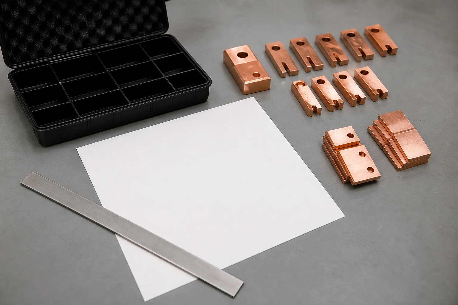
5. Confirm dimensional compatibility. If sourcing from a conductive-components supplier rather than the OEM, provide the supplier with the breaker model, panel model, contact part number, and inspection photographs. The supplier must confirm geometric and material compatibility with the OEM's validated design.
6. Verify that the replacement contact does not change the type-test basis of the assembly. If the OEM documentation does not list the proposed replacement as a validated alternative, the replacement introduces an evidence gap that must be addressed before installation.
Model-specific approved procedures govern all installation, adjustment, and commissioning actions. The workflow above stops at the point of procurement readiness; it does not extend to torque values, contact-resistance setpoints, or gas-handling procedures, all of which require the OEM's service documentation and qualified personnel.
Installation and Failure Risks at the Evidence Boundary
The most consequential failure mode for either contact type is elevated contact resistance that goes undetected. In flat contacts, this typically results from loss of clamping force, surface oxidation, or contamination. The heating is concentrated at the clamping interface and may not be visible externally until thermal damage has propagated to adjacent insulation or bus connections.
In tulip contacts, the equivalent failure mode is spring fatigue across the finger array, often combined with spigot wear. Because the fingers provide redundancy, early-stage degradation can be masked: the remaining healthy fingers carry additional current, accelerating their own wear. By the time contact resistance rises enough to trigger an alarm — if the switchgear is instrumented for it — the entire finger set and the spigot may need replacement.
Both failure modes are detection problems, not geometry problems. The appropriate response is a condition-based inspection protocol defined by the OEM, not a preference for one contact type over the other. When specifying replacement contacts, the procurement engineer should confirm that the replacement components restore the original contact pressure and surface condition, because those are the parameters that determine resistance, not the geometry alone.
A mismatch between contact type and fixed-side interface is a different category of risk entirely. It is a configuration error that can prevent the withdrawable element from reaching its service position, or worse, allow partial engagement that appears correct during racking but produces inadequate contact pressure at rated current. This risk is eliminated by the verification workflow above.
FAQ
What is the main difference between flat contacts and tulip contacts in switchgear?
Flat contacts transfer current across two parallel clamping surfaces pressing against a bus blade, while tulip contacts use an array of spring-loaded fingers engaging a central spigot. The functional difference is in the mating geometry and current-distribution path, but both types must be matched to their specific fixed-side interface in the panel. Neither type is universally superior; each is validated as part of a specific circuit-breaker and panel assembly.
What is the correct way to determine which contact type a circuit breaker requires?
Start with the exact circuit-breaker model and revision, then retrieve the OEM's parts list or manual addendum. ABB's HD4-DR documentation, for example, identifies tulip and clamp contacts as model-specific options for a withdrawable assembly. The contact type is a design constraint set by the OEM, not a field selection. The panel model must also be confirmed, because the fixed-side interface — whether a flat blade or an isolating tulip — must match.
What is the risk of substituting one contact type for the other?
Substituting a flat contact for a tulip contact, or vice versa, changes the mating geometry and invalidates the type-test basis of the switchgear assembly. At minimum, the withdrawable element may not seat correctly. At worst, partial engagement produces high contact resistance and localized heating under load. Any substitution that is not explicitly documented by the OEM as a validated alternative requires a new type-test or engineering assessment to re-establish the evidence basis.
What is the minimum information a supplier needs for a contact replacement RFQ?
The supplier needs the circuit-breaker model and revision, the panel model and configuration, the OEM contact part number, and inspection data showing the current condition of both the movable contact and the fixed-side interface. Without these details, neither the supplier nor the buyer can confirm geometric, dimensional, and performance compatibility. Generic requests that specify only "tulip contact" or "flat contact" without model-specific context carry a significant risk of procurement error.

