

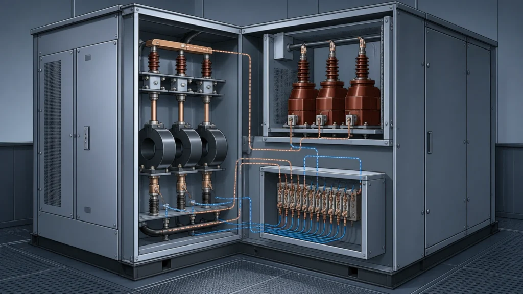
Quick Takeaway
- Confirm the project duty and applicable requirements for Instrument Transformers before selection or service work.
- Use recorded inspection and test evidence instead of unsupported assumptions.
- Keep the final acceptance, maintenance, and handover documents with the equipment record.
An instrument transformer's accuracy class defines how closely its secondary output reproduces the primary signal under specified conditions, and it determines whether the transformer is suitable for revenue metering, protection relaying, or both. Choosing the wrong accuracy class does not simply degrade measurement quality; it can cause billing disputes, protection mis-coordination, or regulatory non-compliance. Before any procurement or replacement decision advances, the questions below give you the structured framework to confirm suitability with your project engineer in the Instrument Transformers context.
Why Accuracy Class Is the Central Selection Variable
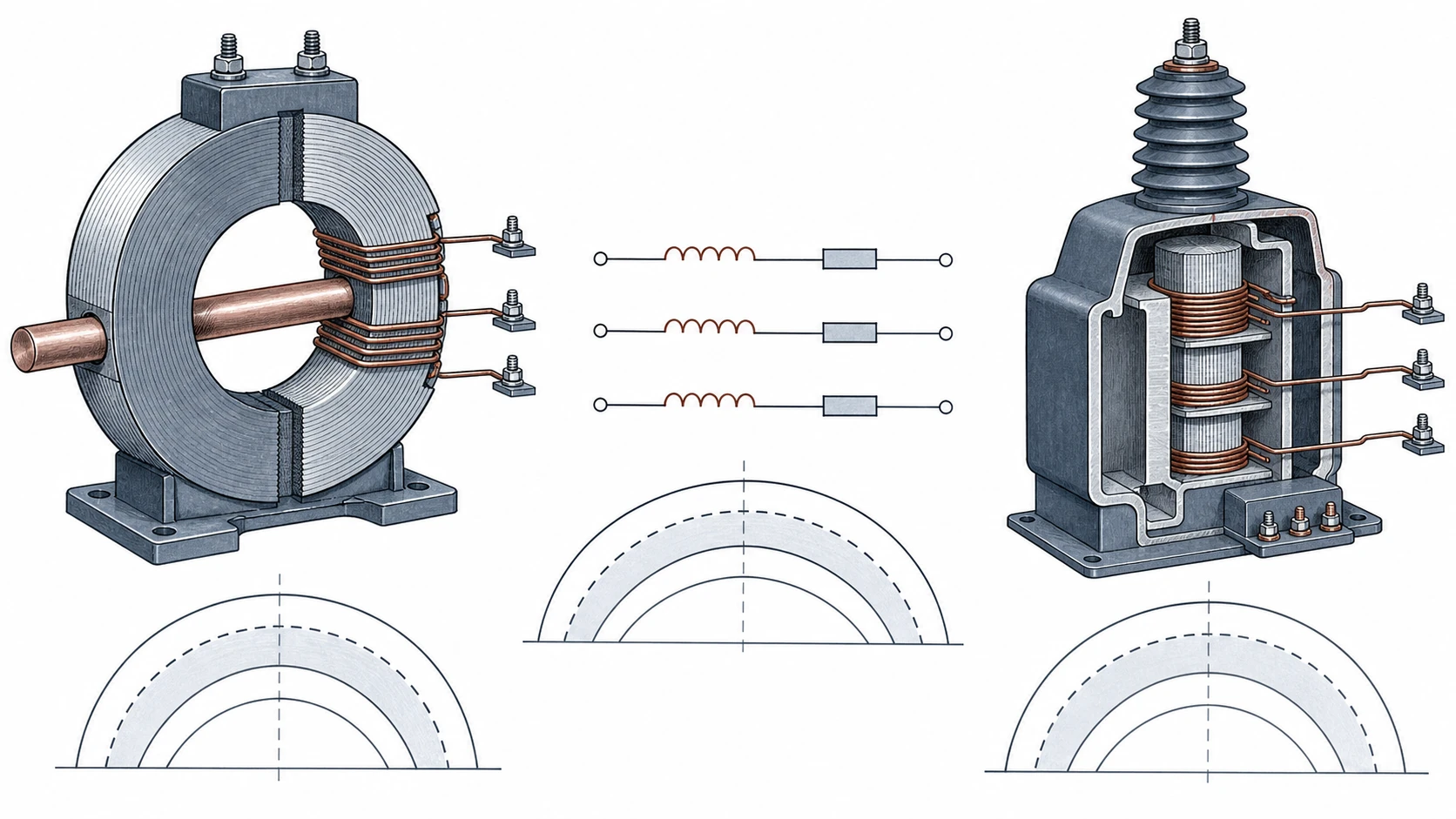
Every instrument transformer sits between a high-voltage or high-current primary circuit and the low-level instruments that depend on its output. The accuracy class tells you the maximum permissible ratio error and phase displacement at defined burden and current or voltage levels. A metering-class current transformer rated 0.2 must hold ratio error within ±0.2 % at rated current and rated burden; a protection-class unit rated 5P must hold ratio error within ±1 % up to its rated accuracy limit factor. These are not interchangeable tolerances. A 0.5-class CT installed where a 0.2-class is specified may pass commissioning tests at rated load yet drift outside limits at low load, exactly the operating point where revenue metering accuracy matters most.
IEC 61869-1:2023 provides general requirements for instrument transformers, including error-limit context for analogue and digital secondary signals used for measuring, protection, and control. It does not by itself tell you which class an application needs. That determination depends on the metering code, protection philosophy, and connected burden, all of which the project engineer confirms.
Metering Versus Protection: The Functional Split
The accuracy-class designation encodes the transformer's intended duty. Metering classes (0.1, 0.2, 0.2S, 0.5, 0.5S, 1.0 for CTs; 0.1, 0.2, 0.5, 1.0, 3.0 for VTs) are optimized to deliver tight error limits at and around rated values, because billing and power-quality measurement depend on fidelity during normal operation. Protection classes (5P, 10P, TPX, TPY, TPZ for CTs; 3P, 6P for VTs) are optimized to maintain known performance up to multiples of rated current or voltage during faults, because relays need a predictable signal under transient overload.
| Parameter | Metering Class (example 0.2S CT) | Protection Class (example 5P20 CT) |
|---|---|---|
| Primary operating range of interest | 1 %–120 % of rated current | Up to 20× rated current (ALF = 20) |
| Ratio error limit at rated current | ±0.2 % | ±1 % |
| Phase displacement limit at rated current | ±10 minutes | ±60 minutes |
| Saturation behavior | Designed to saturate early to protect meters during faults | Designed to avoid saturation up to the accuracy limit factor |
| Connected instrument concern | Revenue meter or power-quality analyzer | Overcurrent, differential, or distance relay |
The "S" suffix on metering classes (0.2S, 0.5S) extends the accuracy requirement down to 1 % of rated current instead of 5 %. This matters for lightly loaded feeders or transformer circuits that often operate well below nameplate. Ask the project engineer whether the expected load profile justifies the S-class premium.
ABB documents indoor instrument-transformer product families covering metering, protection, and external power-supply applications, with varying ratings and configurations. This confirms that manufacturers design and catalog distinct products for each duty. The question for the project engineer is not just which class is specified but whether the transformer can physically serve the burden, thermal rating, and installation envelope in the wider MV Switching Equipment assembly.
Burden, Connected Load, and the Accuracy Interaction
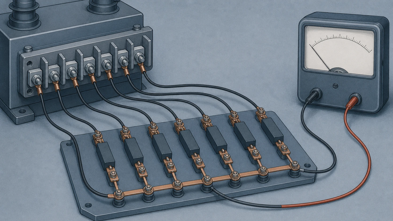
An accuracy class is only valid at or below the rated burden. A 0.5-class VT rated at 50 VA performs within 0.5 % error limits only if the total connected burden, including pilot-wire resistance, does not exceed 50 VA. Exceed that burden and the transformer still functions, but accuracy degrades outside the stated class, often without any visible alarm. Under-burdening can also shift error characteristics, particularly for inductive voltage transformers where magnetizing current becomes a larger proportion of the total load at very light burdens.
Questions to prepare for the project engineer:
- What is the total connected burden in VA at the secondary terminals, including wiring losses?
- Does the burden change between normal operation and fault conditions (relay coils changing impedance)?
- If digital secondary outputs per IEC 61869-1 are used, how is burden defined, and does the merging unit introduce latency or sampling error that the accuracy class does not cover?
These burden questions often expose mismatches that a nameplate accuracy class alone will not reveal.
Standards Scope and Evidence Boundaries
IEC 61869-1:2023 establishes general requirements: it defines terms, specifies how errors are measured, and sets environmental and insulation requirements. Subsequent parts of the series (61869-2 for CTs, 61869-3 for inductive VTs, 61869-5 for capacitor VTs, and others) provide the specific accuracy-class tables, test procedures, and rated values for each transformer type. If your specification references only 61869-1, the project engineer should confirm which type-specific part governs the accuracy-class limits and test requirements.
Regional or utility metering codes may impose accuracy requirements stricter than or different from the IEC baseline. North American practice often references IEEE C57.13 with different class designations (0.3 ANSI metering, C-class and T-class relaying). Confirm with the project engineer which standard edition the project follows and whether dual compliance is needed for export or multi-jurisdiction installations.
What the standards do not tell you is whether a specific manufacturer's product meets the required class at the specific burden, frequency, temperature, and altitude of your installation. That assurance comes from the type-test report and, for revenue metering, often a witnessed routine test. The next section covers what records to request.
Records and Test Data to Request Before the RFQ
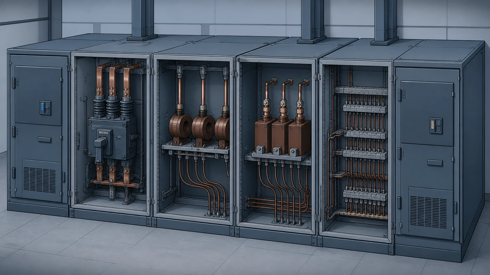
A procurement package that specifies only "0.2-class CT, 50/5 A" leaves too many variables open. Use the instrument-transformer selection-data checklist to confirm or jointly assemble the following data before the request for quotation.
From the project's protection and metering philosophy:
- Accuracy class and rated burden for each winding (a multi-core CT may carry one metering winding and one protection winding with different classes).
- Rated accuracy limit factor (ALF) for protection cores and instrument security factor (Fs) for metering cores.
- Whether extended-range or S-class metering is required based on load-profile analysis.
- Rated insulation level, thermal short-time current, and dynamic peak current requirements.
- System frequency (50 Hz or 60 Hz) and whether the transformer must perform across both.
- Ambient temperature range and altitude if above 1000 m, both of which derate insulation and can shift magnetizing characteristics.
From the manufacturer:
- Type-test certificate to IEC 61869 (or IEEE C57.13) confirming the stated accuracy class at rated and extreme burdens.
- Routine-test results for the specific units shipped, including ratio error and phase displacement at defined percentages of rated current or voltage.
- Burden-versus-accuracy curves showing performance across the expected operating range, not only at the single rated burden point.
- Nameplate data confirming class designation, ALF or Fs, rated burden, and standards compliance.
- If digital outputs are provided, confirmation that the digital accuracy class per IEC 61869-1 is met, including sampling-rate and delay specifications.
This record set lets the project engineer verify that the offered product matches the application before the transformer ships.
Selection and Verification Workflow
Selection follows a logical chain. Start from the application and work toward the product, not the reverse.
1. Identify the purpose: metering, protection, or combined. Combined-duty transformers carry separate cores for each function; a single core cannot be optimized for both metering accuracy and protection transient performance.
2. Determine the accuracy class from the metering code or protection study. The project engineer owns this determination, but procurement should confirm it is documented and traceable.
3. Calculate the total burden including secondary wiring. For long cable runs typical of outdoor switchyards, wiring burden alone can approach or exceed the transformer's rated burden.
4. Check that the rated accuracy limit factor or instrument security factor is consistent with the fault-current level. A 5P20 CT in a system where the maximum fault current is 30 times rated current will saturate before the relay receives a usable signal.
5. Confirm environmental derating. Altitude corrections for insulation and temperature corrections for thermal limits can shift the effective accuracy class if the transformer is marginally rated.
6. Request and compare manufacturer test data against the requirements established in steps 1–5.
At commissioning, secondary injection or primary injection tests verify that the installed transformer meets its accuracy class in situ. Model-specific approved procedures govern these tests; the project engineer or commissioning authority defines the acceptance criteria and pass/fail limits.
Common Failure Risks Linked to Accuracy-Class Misapplication
Accuracy-class errors rarely announce themselves with a tripped breaker. They surface as billing adjustments months later, as protection relays that fail to operate or operate slowly during a fault, or as power-quality data that cannot be reconciled across measurement points.
Specific risks to flag during your review:
- A metering CT with a high instrument security factor (Fs greater than 5) allows fault current to reach connected meters, potentially damaging revenue-grade instruments. The project engineer should confirm that Fs is low enough to protect the metering circuit.
- A protection CT with an accuracy limit factor too low for the prospective fault current saturates during faults. The relay sees a distorted, reduced signal and may delay or fail to trip. The protection study must confirm the ALF against actual fault levels.
- A voltage transformer loaded beyond its rated burden shifts ratio error outside the stated class. Because VT burden is often close to the limit when multiple instruments and relays share one secondary, any added device (a power-quality recorder, a synchrophasor unit) can push the burden over the edge without anyone recalculating.
- Mixing IEC and IEEE class designations on the same project creates ambiguity in test and acceptance criteria. A "0.3-class" CT under IEEE C57.13 is not the same as a "0.2-class" CT under IEC 61869-2; the test points, burden conventions, and error-limit structures differ.
Each of these risks resolves into a question the project engineer can answer before procurement, not after installation.
Preparing for the Technical Review Meeting
Bring the following to the meeting with the project engineer, organized as a single-page summary per transformer position:
- The single-line diagram location and the function each transformer serves at that location.
- The specified accuracy class, burden, ALF or Fs, and the standards reference that governs them.
- The expected operating range as a percentage of rated current or voltage, including minimum sustained load.
- The prospective fault current at that location from the most recent short-circuit study.
- Any environmental or space constraints (altitude, ambient temperature, panel or cell dimensions).
- The manufacturer's offered data sheet and test certificates.
This summary helps the project engineer review suitability without chasing information across multiple documents, alongside the relevant MV switchgear components interface record.
FAQ
What is the difference between a metering-class and a protection-class instrument transformer?
A metering-class instrument transformer is designed to maintain tight ratio-error and phase-displacement limits at and around rated current or voltage, serving revenue metering and power-quality instruments during normal operation. A protection-class instrument transformer is designed to deliver a predictable signal up to high multiples of rated current or voltage during faults, serving relays that must operate under transient overload. A single transformer can carry separate cores for each function, but a single core cannot be optimized for both duties simultaneously.
What is an accuracy limit factor and why does it matter?
The accuracy limit factor is the multiple of rated primary current up to which a protection-class current transformer maintains its stated accuracy. A designation of 5P20 means the CT holds within 5 % composite error at up to 20 times rated current. If the prospective fault current at the installation point exceeds this multiple, the CT saturates and the connected relay receives a distorted signal, which can delay or prevent tripping. The project engineer matches the ALF to the short-circuit study for each CT location.
What is the instrument security factor on a metering CT?
The instrument security factor (Fs) limits how much fault current passes through the metering secondary by defining the current level at which the metering core saturates. A low Fs value (for example, Fs ≤ 5) means the core saturates early during a fault, protecting connected meters from destructive overcurrent. A high Fs value allows more fault energy through to the metering circuit. Specifying Fs is part of the metering-core selection and should be confirmed alongside the accuracy class.
What is the role of IEC 61869-1 in specifying accuracy classes?
IEC 61869-1:2023 provides the general framework for instrument transformers, defining terminology, environmental requirements, insulation levels, and the methodology for evaluating ratio error and phase displacement for both analogue and digital secondary signals. It does not itself contain the accuracy-class tables for specific transformer types. Those tables appear in the type-specific parts of the series, such as IEC 61869-2 for current transformers and IEC 61869-3 for inductive voltage transformers. A complete specification references both the general part and the applicable type-specific part.
What is the risk of exceeding the rated burden on a voltage transformer?
When the total connected burden, including secondary wiring losses, exceeds the rated burden of a voltage transformer, the ratio error and phase displacement can shift outside the limits stated for its accuracy class. The transformer may continue to produce an output without an obvious alarm. The result can be measurement error in metering data, synchrophasor calculations, or voltage-dependent protection functions. Any time a new instrument is added to an existing VT secondary circuit, the cumulative burden should be recalculated and compared against the rated value, a step the project engineer should verify before the change is approved.

