

Quick Takeaway
- Confirm the project duty and applicable requirements for Switchgear Handcarts before selection or service work.
- Use recorded inspection and test evidence instead of unsupported assumptions.
- Keep the final acceptance, maintenance, and handover documents with the equipment record.
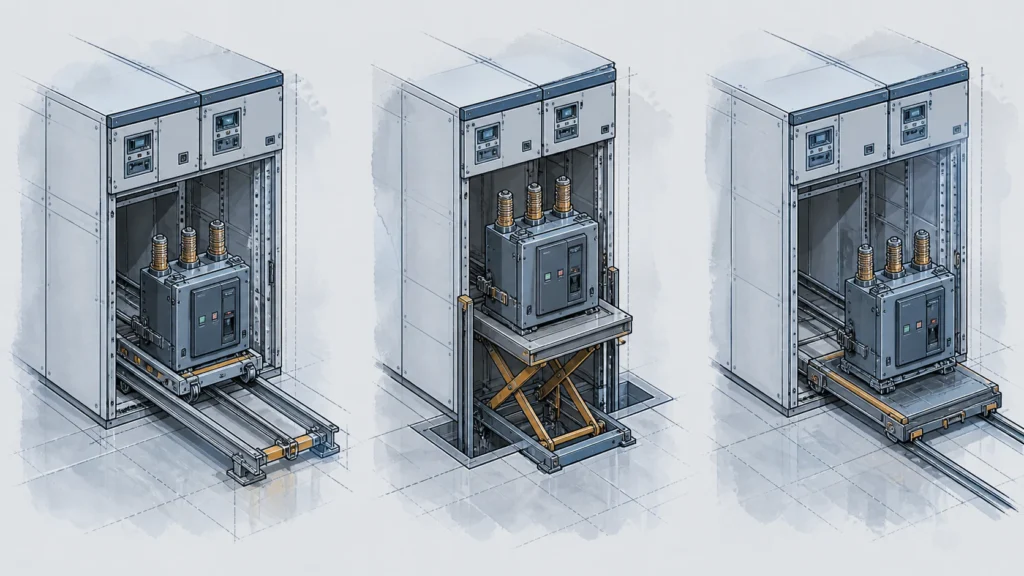
A chassis truck is the permanently integrated racking mechanism that moves a circuit breaker between its connected, test, and disconnected positions inside a switchgear cubicle. A lift truck raises or lowers a breaker to align it with a cubicle's rail entry point. A transfer trolley moves a breaker horizontally across a substation floor between cubicles, storage, or maintenance areas. These three pieces of equipment serve distinct mechanical functions, attach to different interfaces, and are not interchangeable—yet procurement documents and field conversations routinely conflate them, leading to incorrect orders, incompatible deliveries, and delayed outage work. Use the Chassis Trucks & Racking Systems selection context to preserve the role boundary.
| Attribute | Chassis Truck | Lift Truck | Transfer Trolley |
|---|---|---|---|
| Primary motion | In–out racking (horizontal, on cubicle rails) | Vertical lifting/lowering | Horizontal floor transport |
| Installed location | Inside the switchgear cubicle | Positioned at cubicle front or on floor | Moves across substation floor |
| Coupled to breaker during operation | Yes — breaker sits on it permanently | Temporarily, during elevation change | Temporarily, during transport |
| Interface dependency | Cubicle rail profile, racking mechanism, primary isolating contacts | Cubicle door opening dimensions, rail-entry elevation | Floor surface, breaker weight class, cradle or rail compatibility |
| Typical procurement trigger | Cubicle retrofit, breaker-type upgrade, contact-wear replacement | New installation, multi-tier switchgear lineup, maintenance lift need | Fleet maintenance programs, multi-bay lineups, breaker rotation plans |
Why Misidentification Happens and Why It Matters
The three terms overlap in casual use because all three participate in the broader task of "getting a breaker in or out of a cubicle." In some manufacturer literature, "truck" refers generically to any wheeled carrier. In others, "truck" means only the chassis assembly. When a maintenance planner writes "need a truck for Bay 12," the request is ambiguous across all three roles.
The consequences are concrete. A transfer trolley ordered when a chassis truck is needed will arrive without the racking screw, rail guides, or primary-contact interface that the cubicle requires. A chassis truck ordered when a lift truck is needed will not raise the breaker to the correct rail-entry elevation. Either mismatch delays a scheduled outage, ties up capital in return freight, and may force field improvisation that introduces safety risk. Correct identification at the requisition stage eliminates these failure modes.
Chassis Truck: The Integrated Racking Assembly
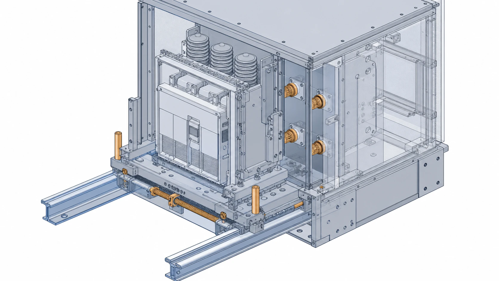
The chassis truck is not a transport device. It is the mechanical subframe on which a withdrawable circuit breaker is permanently mounted. It carries the racking mechanism—typically a lead-screw or lever-driven system—that translates the breaker along the cubicle's internal guide rails between the connected, test, and disconnected positions.
ABB's UniGear ZS1 medium-voltage air-insulated switchgear system uses withdrawable circuit-breaker arrangements where the breaker and its chassis assembly engage primary isolating contacts as the unit racks into the connected position. The chassis truck's rail profile, guide-pin geometry, and contact-engagement sequence are specific to that switchgear platform. A chassis truck from a different switchgear family will not fit, even if the breaker's electrical ratings happen to match.
Schneider Electric's EvoPacT HVX integration guide identifies mechanical fixation and racking interfaces as documented integration considerations. This confirms that the chassis-to-cubicle interface is an engineered match, not a generic dimension. The racking interface includes the rail cross-section, the position-latch detent locations, the shutter-actuation linkage, and the alignment of primary and secondary isolating contacts. Any replacement chassis truck must satisfy all of these simultaneously.
When reviewing a chassis truck for replacement or procurement, the critical data points are: switchgear manufacturer and model designation, cubicle year of manufacture or revision level, breaker type designation, rail profile drawing number, and primary-contact configuration. Without these, a supplier cannot confirm mechanical and electrical compatibility.
Lift Truck: Vertical Positioning Equipment
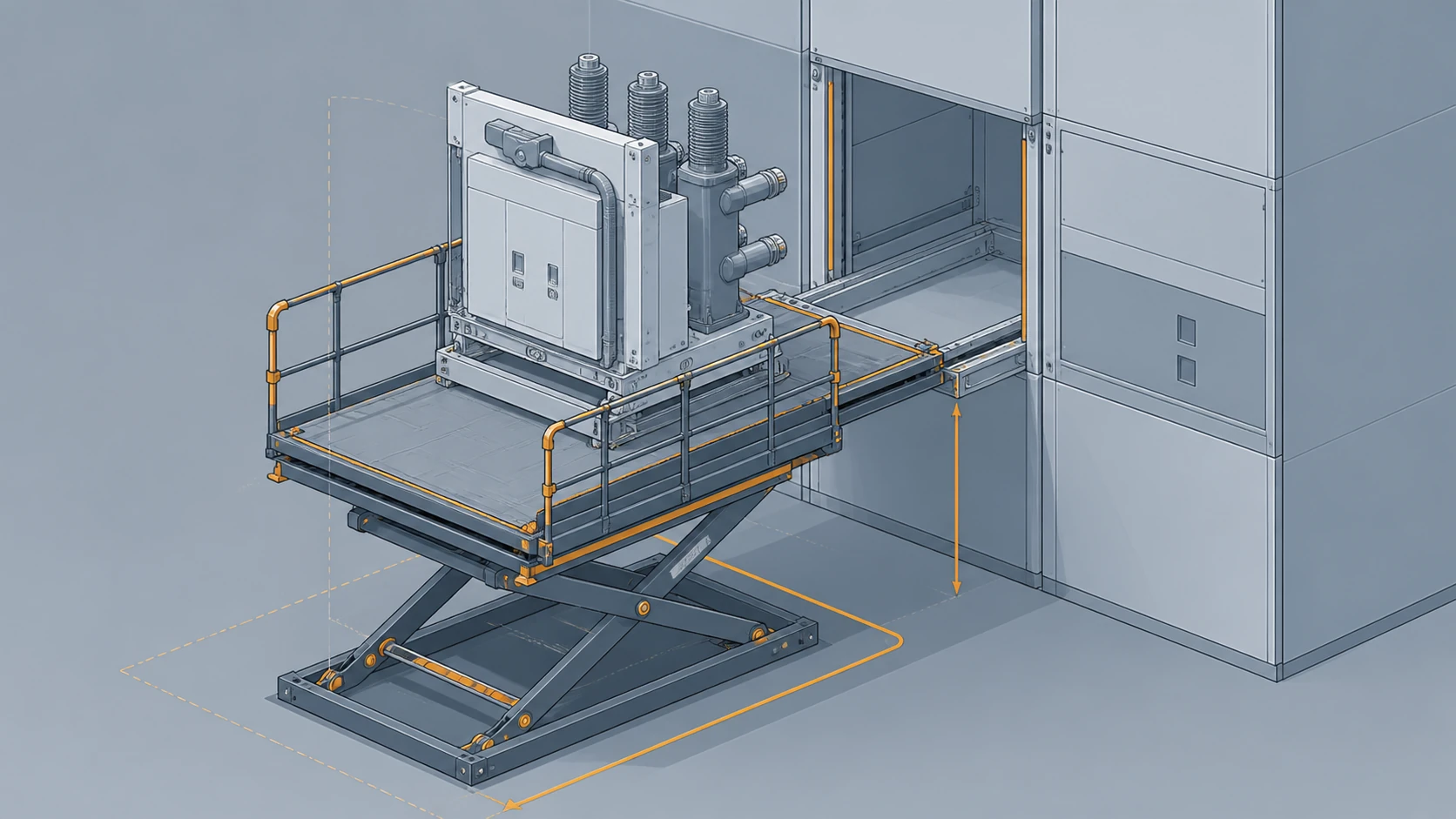
A lift truck is a separate piece of handling equipment used to raise or lower a circuit breaker and its chassis to the elevation of the cubicle's rail-entry opening. In single-tier switchgear lineups where the rail entry is near floor level, a lift truck may not be needed at all. In multi-tier arrangements—where upper-tier cubicles have rail entries well above floor height—a lift truck becomes essential.
The lift truck must accommodate the combined weight of the breaker and chassis assembly, fit within the physical envelope in front of the cubicle, and position the chassis rails to align precisely with the cubicle's entry rails. Alignment tolerances are tight because the chassis must slide smoothly onto the internal guide rails without binding, and the primary isolating contacts must not be damaged by lateral offset during insertion.
Lift trucks are typically specified by the switchgear manufacturer as part of the lineup's handling accessories. Their platform width, rail spacing, elevation range, and load rating are matched to the switchgear family. A generic industrial lift table may have adequate load capacity but will almost certainly lack the correct rail fixtures and alignment features, making it unsuitable without modification. The specific Vacuum Circuit Breakers family record is part of that interface evidence.
Procurement of a lift truck requires: switchgear manufacturer and model, tier configuration of the lineup, maximum breaker-plus-chassis weight in the fleet, and the rail-entry elevation for each tier. If the facility operates multiple switchgear families, each family may require its own lift truck unless a universal adapter system has been validated by the switchgear manufacturer.
Transfer Trolley: Horizontal Floor Transport
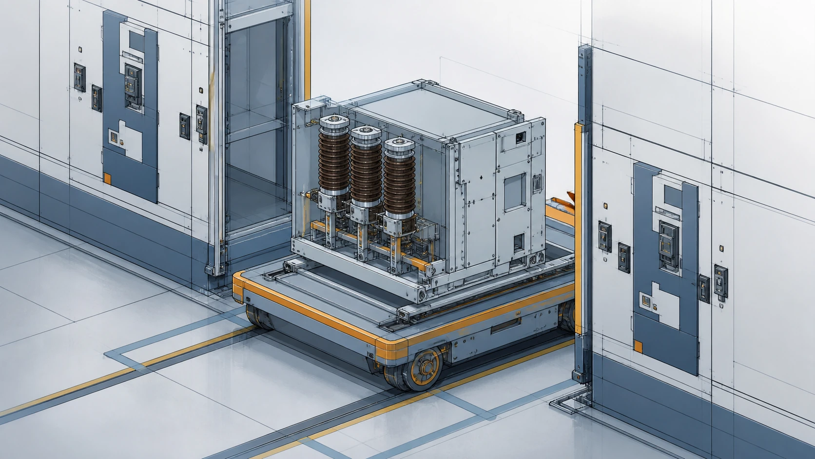
The transfer trolley moves a breaker-and-chassis assembly horizontally across the substation floor. Its role begins after the breaker has been racked out to the disconnected position and removed from the cubicle (with or without a lift truck) and ends when the assembly reaches its destination: a different cubicle, a maintenance bench, or a storage location.
Transfer trolleys are the simplest of the three devices in terms of interface. They need a cradle or rail set that supports the chassis truck's base dimensions, casters or wheels rated for the assembly's weight, and a floor surface that permits rolling transport. Some transfer trolleys are designed with the same rail profile as the cubicle entry so the chassis can roll directly from the cubicle (or lift truck) onto the trolley without manual lifting.
Simplicity does not eliminate specification risk. A trolley with the wrong cradle width will not secure the chassis, creating a tip-over hazard during transport. A trolley with inadequate load rating will deform or fail. And a trolley whose rail profile does not match the chassis-truck base will require manual transfers—lifting the breaker off one set of rails and onto another—adding handling risk and time to every breaker move.
Interface Dependencies and Why "Compatible" Is Not Enough
The reason these three equipment roles cannot be treated as interchangeable lies in their interface chains. Each device connects to different mating surfaces, and each mating surface is defined by the switchgear platform.
The chassis truck interfaces inward to the cubicle: rail profile, racking mechanism, position latches, shutter linkage, primary and secondary isolating contacts. The lift truck interfaces downward to the floor and upward to the chassis-truck base and the cubicle entry: platform geometry, elevation range, rail alignment. The transfer trolley interfaces downward to the floor and upward to the chassis-truck base only: cradle profile, caster load rating, locking mechanism.
A single dimensional mismatch at any point in these chains prevents safe operation. The ABB UniGear ZS1 withdrawable arrangement, for example, is engineered so that the breaker cannot reach the connected position unless the chassis guide pins, rail profile, and contact alignment are all correct. This is a deliberate safety interlock, not a tolerance that can be overcome with force or shimming. The Schneider EvoPacT HVX integration guide documents mechanical fixation and racking interfaces as separate categories of integration consideration, reinforcing that each interface must be validated independently.
When evaluating compatibility, the question is not "does this device fit?" but rather "does this device satisfy every interface in its chain for this specific switchgear platform, cubicle revision, and breaker type?" If any interface cannot be confirmed from documentation, the item should not be ordered without manufacturer verification. Treat that review as part of the broader MV Switching Equipment record.
Identification Evidence: What to Collect Before an RFQ
Before issuing a request for quotation for any of these three equipment types, the following evidence must be assembled. Missing any of these data points risks receiving an incompatible item.
For a chassis truck replacement or spare: the switchgear manufacturer, switchgear model and revision, cubicle serial number or drawing reference, breaker type designation, rail profile drawing number or sample measurement, primary-contact configuration, and racking-mechanism type. Photographs of the existing chassis truck showing the rail profile, guide pins, racking screw or lever, and nameplate are valuable verification aids.
For a lift truck: the switchgear manufacturer and model, the tier configuration and rail-entry elevations for each tier, the maximum breaker-plus-chassis weight, the cubicle front-opening dimensions, and any floor-space constraints in front of the lineup. If the facility has existing lift trucks for other switchgear families, their specifications should be included so the supplier can assess whether a universal solution is feasible.
For a transfer trolley: the chassis-truck base dimensions and rail profile, the maximum assembly weight, the floor surface type and condition, the transport distances involved, and any doorway or aisle-width constraints along the transport path. If breakers will be rolled directly from the cubicle or lift truck onto the trolley, the rail-to-rail transition geometry must be confirmed.
When the Wrong Equipment Arrives: Failure Modes and Recovery
Ordering the wrong equipment type produces predictable failure patterns that are worth understanding because they clarify the distinctions further.
A transfer trolley delivered in place of a chassis truck will have no racking mechanism, no primary-contact interface, and potentially no matching rail profile. The breaker cannot be installed in the cubicle using this equipment. Recovery requires sourcing the correct chassis truck, which may involve lead times of weeks or months for obsolete switchgear families.
A chassis truck delivered in place of a lift truck cannot raise the breaker to an upper-tier entry point. It sits at floor level. If the maintenance team attempts to use a generic lift table or forklift to raise the assembly, they risk misalignment, contact damage, and personnel injury. Recovery requires either sourcing the correct lift truck or engineering a validated adapter—neither of which is a same-day solution.
A lift truck delivered in place of a transfer trolley may technically support the breaker's weight, but it is not designed for horizontal floor transport. Its casters, if any, are sized for fine positioning, not rolling across a substation floor. Attempting to use it as a trolley risks caster failure, instability, and damage to the breaker assembly.
In all three cases, the root cause is the same: the equipment was specified by function ("move the breaker") rather than by role and interface. Specifying by role, interface, and platform eliminates the ambiguity.
Verification Workflow for Incoming Equipment
When a chassis truck, lift truck, or transfer trolley arrives at site, verification should confirm role, interface, and platform compatibility before the item is accepted into inventory.
For a chassis truck: confirm the nameplate matches the ordered switchgear platform and breaker type. Inspect the rail profile against a reference drawing or the mating cubicle rails. Verify that the racking mechanism operates freely through its full travel. Check the primary-contact fingers or tulips for damage, correct count, and correct spacing. Model-specific approved procedures from the switchgear manufacturer govern contact-alignment verification and any adjustment that may be needed.
For a lift truck: confirm the nameplate and load rating. Verify that the platform rail fixtures match the chassis-truck base profile. Cycle the elevation mechanism through its full range and confirm it reaches the required tier-entry elevations. Check that the platform fits within the cubicle front-opening envelope with adequate clearance.
For a transfer trolley: confirm load rating and cradle dimensions against the chassis-truck base. Roll the trolley across a representative floor section to verify caster performance. If the trolley is designed for direct rail-to-rail transfer, test the transition geometry against the cubicle exit or lift-truck platform.
Any discrepancy found during this verification should halt acceptance and trigger a supplier inquiry before the equipment is placed into service or storage. Use the VCB replacement information checklist to start the evidence pack.
FAQ
What is a chassis truck in switchgear?
A chassis truck is the mechanical subframe permanently attached to a withdrawable circuit breaker inside a switchgear cubicle. It carries the racking mechanism and guide-rail interface that move the breaker between connected, test, and disconnected positions. The chassis truck is specific to the switchgear platform: its rail profile, racking hardware, and primary-contact geometry must match the cubicle design. It is not a transport or lifting device.
What is the difference between a lift truck and a transfer trolley for switchgear breakers?
A lift truck raises or lowers a breaker-and-chassis assembly vertically to align with a cubicle's rail-entry elevation, which is essential in multi-tier switchgear lineups. A transfer trolley moves the assembly horizontally across the substation floor between cubicles, maintenance areas, or storage. They serve perpendicular axes of motion, connect to different interface points, and are specified using different dimensional and load-rating data.
What information is needed to order a replacement chassis truck?
At minimum: the switchgear manufacturer and model designation, cubicle serial number or drawing reference, breaker type, rail-profile drawing number or measured dimensions, primary-contact configuration, and racking-mechanism type. Photographs of the existing chassis truck—particularly the rail profile, guide pins, and nameplate—help suppliers confirm compatibility. Without this data, a supplier cannot guarantee that the replacement will fit the cubicle's withdrawable interface.
What happens if the wrong type of equipment is ordered?
The equipment will not perform the required function. A transfer trolley cannot rack a breaker into a cubicle because it lacks the racking mechanism and contact interface. A chassis truck cannot elevate a breaker to an upper-tier entry point. A lift truck is not designed for floor transport across a substation. Each mismatch delays outage work by the lead time required to source the correct item, which can be weeks or months for older switchgear platforms. Specifying equipment by its role, interface chain, and switchgear platform—not by a generic function description—prevents these errors.

