

Quick Takeaway
- Confirm the project duty and applicable requirements for Auxiliary and Magnetic Blowout Switches before selection or service work.
- Use recorded inspection and test evidence instead of unsupported assumptions.
- Keep the final acceptance, maintenance, and handover documents with the equipment record.
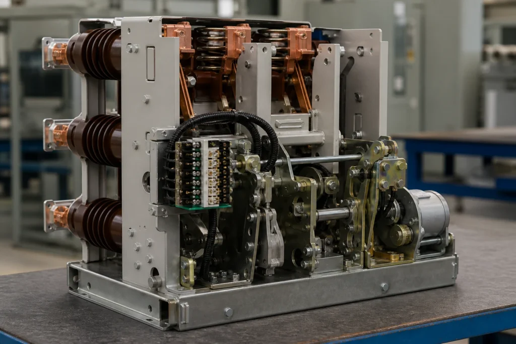
A circuit-breaker auxiliary switch reports the position of the main contacts — open or closed — to external control, indication, and interlocking circuits. A motor limit switch monitors a mechanical travel endpoint, most commonly the state of the spring-charging mechanism, and cuts power to the motor once the closing springs are fully charged. These are not interchangeable names for one device; they sense different physical conditions, operate at different points in the breaker's duty cycle, and feed different circuits. Getting the distinction wrong in an inquiry can send the wrong part number to a site, delay commissioning, or leave a protection scheme blind to breaker state. The Vacuum Circuit Breakers category provides the broader equipment context.
| Characteristic | Auxiliary Switch | Motor Limit Switch |
|---|---|---|
| **What it senses** | Main-contact position (open / closed) | Mechanical endpoint — typically spring-charge completion |
| **Actuation source** | Breaker operating shaft or toggle linkage | Spring-charging motor cam or gear train |
| **Typical circuit role** | Status indication, interlocking, trip-circuit supervision, anti-pump | Motor de-energization, charging-cycle control |
| **Operated states** | Two primary: contacts-open, contacts-closed (multi-stage designs add 52a/52b timing) | Two primary: springs discharged (motor running), springs charged (motor off) |
| **Failure consequence** | Loss of remote indication or interlock; possible breaker lockout by protection relay | Motor stalls or runs continuously; spring overcharge or motor burnout |
Why the Distinction Matters Before You Write an RFQ
Procurement errors most often originate in the inquiry, not in the warehouse. When a request simply says "breaker switch" or treats the two names as synonyms, the supplier has to guess which function is needed. That guess propagates through quoting, approval, and delivery. By the time the part arrives on site it may bolt into the same mounting but sense the wrong condition entirely.
Schneider Electric's Masterclad MV switchgear instruction bulletin makes the separation explicit: the auxiliary switch is described as a multi-stage switch for circuits that depend on main-contact position, while the motor limit switch controls spring-charging motor energization and de-energizes the motor when the closing springs are charged. These are different devices on different shafts, serving different control loops. An inquiry that conflates them forces the vendor to interpret — or worse, to ship the more common of the two and hope it fits.
ABB's VM1 vacuum circuit-breaker instruction manual reinforces the point structurally. Its wiring diagrams separately identify auxiliary switches on the actuating shaft and limit switches for the withdrawable-part test and service positions. The limit switches there respond to the truck's physical location in the compartment, not to the state of the main contacts. This is a second, distinct use of "limit switch" in the same breaker — proof that the label alone is ambiguous without the operated state and mounting context.
Functional Mechanism: How Each Switch Operates
Auxiliary Switches
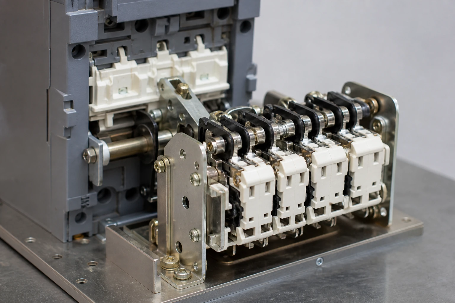
An auxiliary switch is mechanically coupled to the breaker's main operating linkage. When the breaker trips or closes, the linkage drives a cam or slider that toggles the auxiliary switch's contact stages. A typical multi-stage auxiliary switch provides both "a" contacts (closed when the breaker is closed) and "b" contacts (closed when the breaker is open), often designated 52a and 52b in accordance with ANSI device numbering. Some designs include early-make or late-break stages that change state slightly before or after the main contacts, enabling precise sequencing for anti-pump, trip-circuit supervision, or bus-transfer schemes.
The key point: the auxiliary switch has no awareness of spring charge, truck position, or motor state. It answers one question — are the main contacts open or closed? Every circuit that needs that answer depends on this switch.
Motor Limit Switches
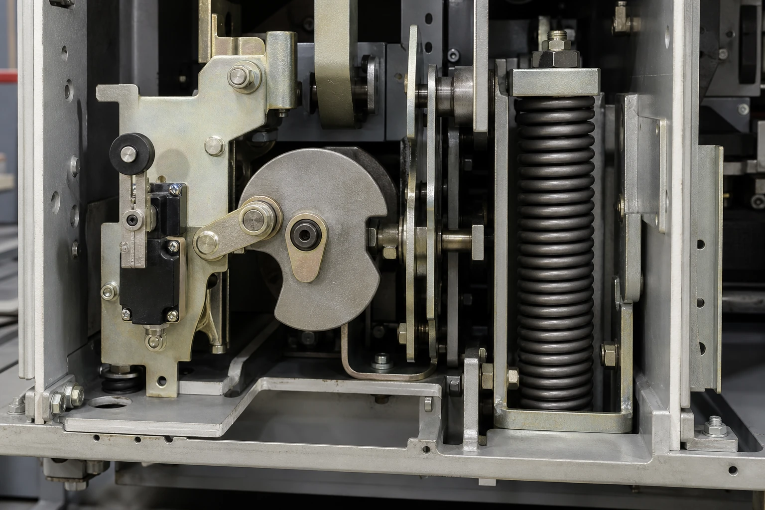
A motor limit switch is mechanically coupled to the spring-charging mechanism, usually through a cam on the charging-motor gear train. Its sole job is to remove power from the charging motor once the closing springs reach the fully charged position. Without it, the motor would continue to run against a fully compressed spring set, stalling and eventually burning out the motor winding or damaging the mechanical stop.
The limit switch does not know whether the breaker is open or closed. It knows whether the springs are charged or discharged. That single piece of information governs motor control and, in some designs, feeds a "ready to close" indication to the control room.
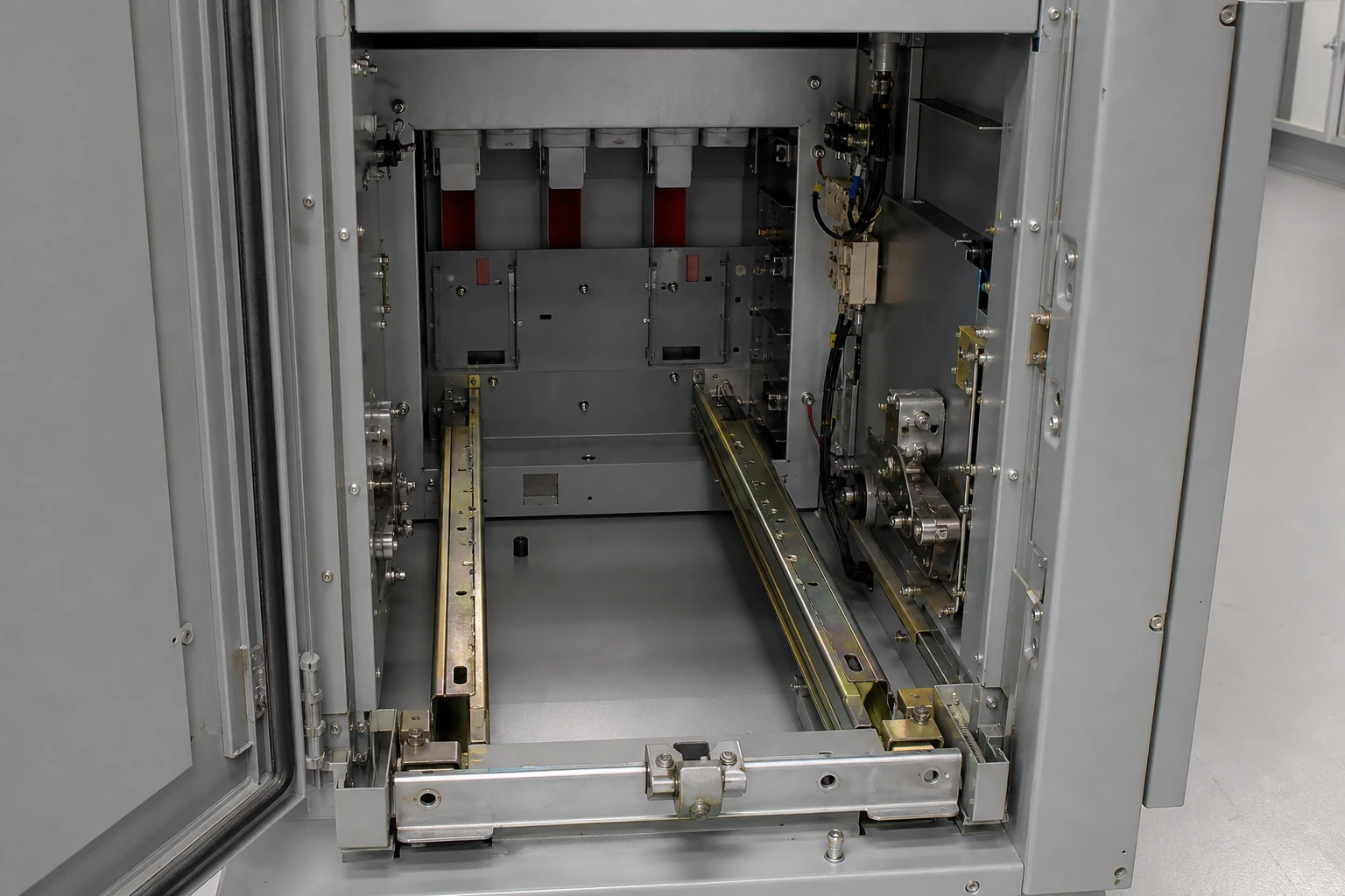
In withdrawable breakers, an additional category of limit switch may sense the truck's racking position — connected, test, or disconnected. ABB's VM1 documentation identifies these as limit switches for test and service positions, distinct from both the auxiliary switch and the motor limit switch. When specifying a replacement, the truck-position limit switch must not be confused with the motor limit switch even though both carry the "limit switch" label.
Mapping the Operated State to the Correct Device
The most reliable way to avoid confusion in an inquiry is to state the operated state the switch must detect, rather than relying on the common name alone.
| Operated State to Detect | Correct Device | Typical Mounting Location |
|---|---|---|
| Main contacts open or closed | Auxiliary switch | Operating shaft or toggle linkage |
| Closing springs fully charged | Motor limit switch | Charging-motor cam or gear train |
| Truck in test position | Position limit switch | Withdrawable-unit rail or compartment |
| Truck in service (connected) position | Position limit switch | Withdrawable-unit rail or compartment |
State the operated condition, the breaker model, the existing part number if available, and the number of NO/NC contact stages needed. That quartet eliminates nearly all ambiguity from the inquiry.
Interface and Configuration Dependencies
Auxiliary switches and motor limit switches connect to fundamentally different control loops, and their contact ratings reflect that difference.
Auxiliary switch contacts typically carry low-level DC or AC signals to relays, PLCs, SCADA RTUs, and indicator lamps. The contact rating must match the worst-case interrupting duty of the connected circuit — often a relay coil with an inductive kick at de-energization. Multi-stage auxiliary switches may need to be configured with the correct a/b contact assignment for the protection scheme; reversing a stage can invert a breaker-failure relay's logic.
Motor limit switch contacts sit in the motor-power circuit or its control relay circuit. They interrupt a running motor load, which means arc energy and contact erosion patterns differ from those of a signal-level auxiliary contact. Replacing a motor limit switch with an auxiliary switch of the same form factor risks contact welding under motor-start inrush, even if the switch physically mounts in the same location.
Before specifying either switch, capture the following interface data:
- Control voltage and current through the contacts (DC or AC, nominal and inrush)
- Number and configuration of contact stages (NO, NC, changeover)
- Mounting method and shaft engagement (keyed, direct-drive, cam-operated)
- Wiring termination style (screw, compression, blade)
Standards and Evidence Boundaries
IEC 62271-100 and IEEE C37.04 / C37.09 govern circuit-breaker ratings and testing, including auxiliary circuit requirements. IEC 62271-100 Annex A addresses the auxiliary and control circuits of high-voltage switchgear and references contact-duty classifications (resistive, inductive, motor) that directly affect whether a given switch suits a particular circuit role.
These standards define performance and test obligations. They do not prescribe a single naming convention across manufacturers. "Auxiliary switch," "limit switch," "position switch," and "status switch" can all appear in OEM documentation for devices that fall into the two or three functional categories discussed here. The standard's value in an inquiry is as a shared reference for contact rating and duty class, not as a parts dictionary. Related evidence-led guidance is available in the Technical Articles library.
Model-specific approved procedures govern installation torque, shaft alignment, cam timing, and contact-gap verification. These procedures vary by manufacturer and breaker type. State in the inquiry which OEM procedures you hold so the supplier can confirm mechanical and dimensional compatibility.
Selection and Verification Workflow for Replacement or New Specification
A single workflow covers both the procurement decision and the incoming-inspection check.
1. **Identify the function.** Determine whether the circuit requires main-contact position, spring-charge state, or truck-position sensing. If the existing device is being replaced, trace its wiring on the OEM schematic — Schneider's Masterclad bulletin and ABB's VM1 manual both segregate these functions on separate drawing sheets.
2. **Record the operated state.** Note the physical condition that must toggle the switch: breaker closed, springs charged, truck racked in, etc.
3. **Capture the electrical interface.** Record control voltage, current, duty class (resistive, inductive, motor), and the number of NO/NC stages.
4. **Capture the mechanical interface.** Record mounting orientation, shaft size and engagement method, cam profile if applicable, and terminal style.
5. **Verify the candidate part.** When the replacement arrives, confirm that the datasheet lists the correct operated state, contact rating, and mechanical mounting. A switch that mounts correctly but senses the wrong condition will pass a visual inspection and fail functionally.
6. **Confirm on the OEM schematic.** Cross-reference the replacement part against the wiring diagram for the specific breaker serial number. Wiring changes between production runs are common in MV switchgear.
Common Failure Modes That Trace to Misidentification
**Motor stall from missing limit switch function.** If an auxiliary switch is installed where a motor limit switch should be, the switch changes state on breaker open/close rather than on spring charge completion. The charging motor never receives a stop signal. The result is motor overheating, blown motor fuses, or mechanical damage to the spring mechanism.
**False breaker-open indication.** If a motor limit switch is installed where an auxiliary switch should be, the control room sees "springs charged / discharged" as if it were "breaker closed / open." A breaker-failure relay watching that contact may initiate an unnecessary bus trip, or worse, may fail to detect an actual breaker failure.
**Contact welding under motor inrush.** Auxiliary switch contacts rated for signal-level duty can weld shut under the inrush current of a spring-charging motor. The motor then cannot be de-energized by the limit switch circuit, reproducing the stall condition described above.
Each of these failures is preventable at the inquiry stage by stating the operated condition and the circuit duty class. A verified evidence package can then support a model-specific request through the product range.
What to Include in the Inquiry Document
Merge the selection data into a single specification line per switch when writing the inquiry or RFQ. A concise format:
- Breaker OEM, model, and vintage
- Switch function: main-contact position / spring-charge limit / truck-position limit
- Operated state: e.g., "closed when breaker is closed" or "open when springs are fully charged"
- Contact configuration: number of stages, NO/NC per stage
- Electrical rating: voltage, continuous current, duty class
- Mechanical fit: mounting type, shaft engagement, terminal style
- Existing OEM part number (if known)
- Applicable OEM instruction bulletin or drawing number
This format lets the supplier confirm function, fit, and rating in a single review pass. It eliminates the back-and-forth that starts with "do you mean the aux switch or the limit switch?"
FAQ
What is the primary functional difference between a limit switch and an auxiliary switch in switchgear?
An auxiliary switch senses the position of the breaker's main contacts — open or closed — and feeds that status to control, indication, and interlocking circuits. A limit switch senses a mechanical endpoint, most commonly the fully charged state of the closing springs, and de-energizes the spring-charging motor. They are actuated by different mechanisms, serve different control loops, and are not interchangeable even when they share a similar form factor.
What is the risk of specifying the wrong switch type in a replacement inquiry?
The immediate risk is functional failure. An auxiliary switch installed in a motor limit switch position will not stop the charging motor because it responds to main-contact position, not spring state. A motor limit switch installed in an auxiliary switch position will send spring-charge status to circuits expecting breaker-position status, potentially causing false alarms or missed breaker-failure detection. The procurement risk is delay: the wrong part must be returned, reordered, and reshipped.
What is the role of the limit switch in withdrawable circuit-breaker compartments?
In withdrawable designs, position limit switches sense whether the breaker truck is in the connected (service), test, or disconnected position. ABB's VM1 instruction manual identifies these as separate limit switches from both the auxiliary switch and the motor limit switch. They feed interlocks that prevent racking under load or closing the breaker when the truck is not fully engaged. When specifying these, state the truck position each switch must detect.
What is the correct way to describe the operated state when requesting a quotation?
State the physical condition that causes the switch to change state — for example, "contacts close when the breaker main contacts are in the closed position" for an auxiliary switch, or "contacts open when the closing springs reach the fully charged position" for a motor limit switch. Pair this with the contact configuration (NO/NC, number of stages) and the circuit duty class (resistive, inductive, motor). This removes naming ambiguity and lets the supplier match function, not just form factor.
What is the standard reference for auxiliary contact duty classification in MV switchgear?
IEC 62271-100 addresses auxiliary and control circuit requirements for high-voltage switchgear, including contact-duty classifications that distinguish resistive, inductive, and motor loads. IEEE C37.04 and C37.09 provide parallel rating and test frameworks. These standards define performance requirements and can be cited in an inquiry to specify the duty class a replacement switch must satisfy.

