

Quick Takeaway
- Confirm the project duty and applicable requirements for Instrument Transformers before selection or service work.
- Use recorded inspection and test evidence instead of unsupported assumptions.
- Keep the final acceptance, maintenance, and handover documents with the equipment record.
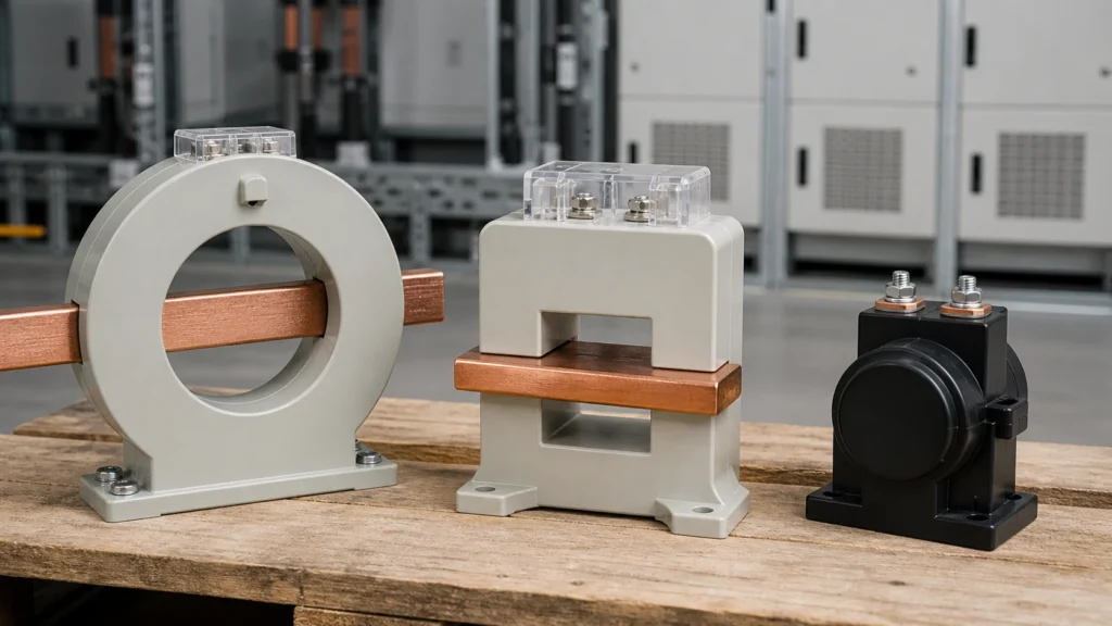
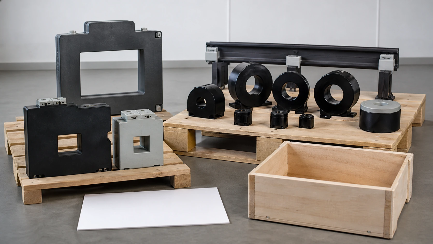
A window current transformer has an open aperture through which the primary conductor passes, a bar current transformer includes a fixed primary bar through the core, and a wound current transformer contains a multi-turn primary winding inside the enclosure. Selecting among them is not a performance question first — it is an identification question, because the correct construction depends on the physical interface (cable, busbar, or conductor size), the mounting arrangement, and the system current rating, all of which must be confirmed from an OEM drawing or nameplate record before a quotation request or replacement decision makes sense. The surrounding MV Switching Equipment assembly supplies essential interface context.
| Feature | Window CT | Bar CT | Wound CT |
|---|---|---|---|
| Primary conductor | External; user-supplied cable or busbar threaded through aperture | Integral bar fixed through the core | Integral multi-turn winding |
| Typical primary current range | Wide; set by conductor and turns ratio | Medium to high (often 100 A and above) | Low to medium (often below 100 A) |
| Physical interface | Aperture diameter or window dimensions must clear the conductor | Bolt-on bar terminals; busbar or cable lug connection | Dedicated primary terminals (P1, P2) |
| Mounting dependency | Panel or busbar bracket; conductor supports the mechanical load | CT body mounts to busbar structure or panel; bar carries the current path | Panel or DIN-rail; self-contained unit |
| Replacement identification priority | Aperture size, conductor OD or busbar cross-section | Bar dimensions, terminal orientation, bolt pattern | Terminal arrangement, turns ratio, winding resistance |
Why Construction Identification Precedes Specification
Procurement teams sometimes start with electrical ratings — ratio, burden, accuracy class — and treat the physical format as secondary. That sequence introduces risk. A window CT with the correct ratio but an aperture 5 mm too small for the existing cable will not install without rework. A bar CT with the correct rating but the wrong terminal orientation will not bolt into the existing busbar spacing. A wound CT ordered to replace a window CT may arrive with primary terminals that have no meaningful connection point in the existing panel.
The physical interface locks the construction choice before accuracy class or burden matter. ABB documents block, bus, and cable current-transformer designs with differing physical interfaces, reinforcing that the drawing, conductor or busbar or cable interface evidence, and mounting evidence must be assembled before identifying a construction or requesting a quotation. This principle applies regardless of manufacturer. The product-family requirements remain subject to IEC 61869-2.
Window CT: Identification and Interface Questions
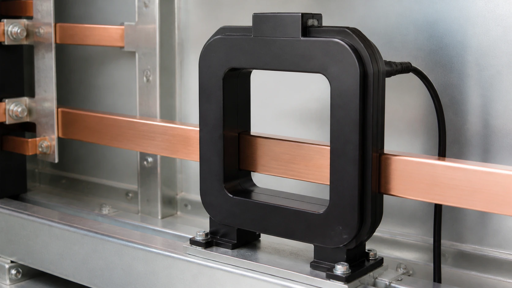
A window (or toroidal) current transformer is the most common indoor type for retrofit and panel applications. Its defining feature is the absence of an integral primary: the core and secondary winding form a ring or rectangle, and the primary conductor — a cable, a busbar, or a single pass of a large conductor — threads through the opening.
Before selecting or replacing a window CT, the following interface evidence must be confirmed from the existing installation drawing or physical inspection record.
Aperture geometry. The window may be circular or rectangular. A circular window is defined by its inner diameter. A rectangular window is defined by height and width. The conductor or busbar that passes through it must clear the aperture with enough margin for insulation, air clearance, and any future re-pull of cable.
Number of primary turns. A single pass of the conductor through the window gives a 1-turn primary, and the nameplate ratio applies directly. Passing the conductor through the window multiple times multiplies the effective primary turns, changing the effective ratio. The installed turn configuration must be recorded before specifying a replacement, because the nameplate ratio alone does not describe the operating ratio if multiple passes were used.
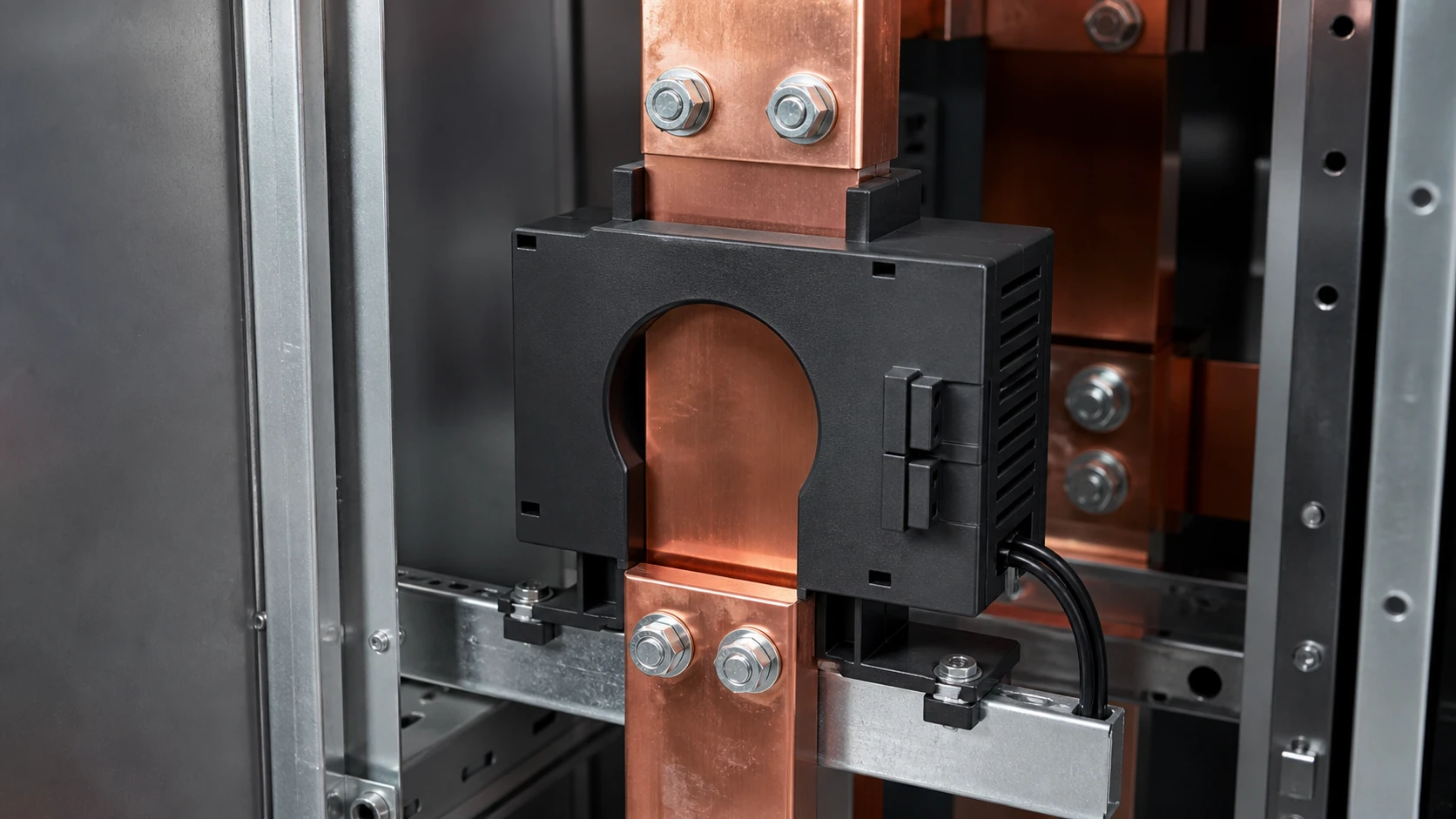
Mounting method. Window CTs mount by clamping to a busbar, bolting to a panel bracket, or resting on a cable tray support. The mounting hardware is usually separate from the CT body. A replacement CT must match or adapt to the existing mounting arrangement, which means the mounting hole pattern, foot dimensions, or clamp style must be documented.
Conductor interface. The CT does not connect electrically to the primary conductor; it surrounds it. This means there are no primary terminals to match. However, the secondary terminals (S1, S2, and any tap terminals) must match the wiring destination, polarity convention, and terminal size of the existing installation. For related evidence-led guidance, consult the Technical Articles library.
Bar CT: Identification and Interface Questions
A bar current transformer integrates a conductive bar — the primary — through the core. The primary conductor is part of the CT itself. This construction suits busbar and high-current cable-lug installations where the system current is high enough that a single-turn bar primary is practical, and where the mechanical interface is a bolted connection to the system busbar or cable lugs.
Bar dimensions and terminal orientation. The bar has a defined cross-section (width × height), length, and hole pattern for bolting. The existing busbar spacing, bolt-hole centers, and bar orientation (vertical or horizontal) must match the replacement CT. A mismatch in any of these dimensions prevents installation.
Current rating and thermal path. Because the bar carries the full primary current continuously, its cross-section is sized for thermal performance. The rated primary current on the nameplate corresponds to a specific bar size. Substituting a CT with a different bar cross-section, even if the ratio matches, changes the thermal behavior and may violate the continuous thermal current rating.
Mounting and enclosure clearance. Bar CTs are typically mounted inline with the busbar run. Their body depth (the dimension perpendicular to the bar axis) determines whether they fit within the enclosure or switchgear compartment. This dimension must be checked against the available depth in the existing cubicle or panel. The product range is suitable for initial family navigation only; it cannot replace drawing verification.
Wound CT: Identification and Interface Questions
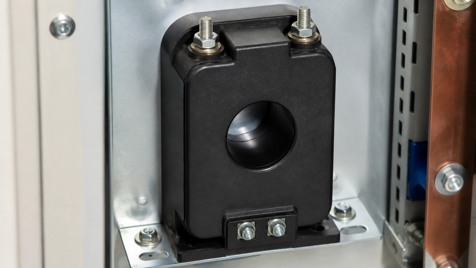
A wound current transformer contains both a multi-turn primary winding and a secondary winding inside a single enclosure. Both P1/P2 (primary) and S1/S2 (secondary) terminals are brought out. This construction is used at lower primary currents — where a single-turn primary would require an impractically large core to achieve the needed ratio — or where the primary conductor is small enough that integrating it into the CT body is practical.
Primary terminal rating and connection method. Because the wound CT has dedicated primary terminals, the cable or busbar connecting to those terminals must be compatible in size, lug type, and torque specification. The terminal ampacity must match the system current, including any overload or short-time thermal rating.
Turns ratio confirmation. Unlike window and bar CTs, where the primary turn count is either one (bar, single-pass window) or user-configured (multi-pass window), the wound CT's turns ratio is fixed at manufacture. The nameplate ratio cannot be altered in the field. This means the ratio must be confirmed exactly against the system requirement before ordering.
Physical size and weight. Wound CTs at lower ratios can be compact and light, suitable for DIN-rail mounting. At higher ratios or higher accuracy classes, they grow larger and may require panel-mount brackets. The existing mounting footprint must be confirmed.
Standards and Evidence Boundaries
IEC 61869-2 applies to inductive current transformers for measuring instruments and protective devices. It defines accuracy classes, burden ratings, and test requirements that apply across all three construction types — window, bar, and wound. However, IEC 61869-2 does not prescribe which construction to use for a given application. Construction selection is an interface and installation decision governed by the physical evidence of the existing system: conductor size, mounting arrangement, enclosure clearance, and terminal interface.
When using IEC 61869-2 ratings to compare candidate CTs, confirm that the accuracy class and rated burden correspond to the actual connected burden of the metering or protection circuit. A CT that meets class 0.5 at 5 VA burden does not guarantee class 0.5 performance if the connected circuit imposes 10 VA.
The standard defines rated insulation levels, rated short-time thermal current (Ith), and rated dynamic current (Idyn). These ratings must be confirmed against the system fault-level study, not assumed from previous installation records alone, because system fault levels may have changed since the original CT was installed.
Pre-RFQ Data Assembly: What to Gather Before Requesting a Quotation
Merging the identification questions above into a single evidence checklist reduces the risk of ordering the wrong construction, the wrong interface, or the wrong rating.
Construction type. Confirm window, bar, or wound from the existing nameplate, drawing, or physical inspection. If the nameplate is illegible, the physical evidence — presence or absence of primary terminals, presence or absence of an open aperture, presence or absence of an integral bar — resolves the construction type.
Physical interface record. For a window CT: aperture dimensions and conductor size. For a bar CT: bar cross-section, length, bolt pattern, terminal orientation. For a wound CT: primary terminal type, size, and connection method.
Mounting footprint. Hole pattern, foot dimensions, bracket type, and available enclosure depth.
Electrical ratings. Rated primary current, rated secondary current (1 A or 5 A), ratio, accuracy class, rated burden, rated insulation level, rated short-time thermal current, and rated dynamic current.
System evidence. Single-line diagram, fault-level study, and connected burden calculation.
Polarity and terminal markings. Confirm the polarity convention (P1/P2, S1/S2 or equivalent markings) and the wiring direction to the connected instrument or relay.
Operating environment. Indoor or outdoor, ambient temperature range, altitude, and any contamination or humidity conditions that affect insulation requirements.
Any quotation request that omits the physical interface evidence — the aperture size, bar dimensions, or primary terminal arrangement — forces the supplier to assume, and assumptions at the interface level result in CTs that arrive on site and do not fit.
FAQ
What is the difference between a window CT, a bar CT, and a wound CT?
A window CT has an open aperture and no integral primary conductor; the system cable or busbar passes through the opening. A bar CT includes a fixed conductive bar as the primary, bolted directly into the busbar run. A wound CT has a multi-turn primary winding with dedicated P1/P2 terminals, used at lower currents where a single-turn primary would be impractical.
What is the first question to ask before replacing a current transformer?
Identify the construction type — window, bar, or wound — from the existing nameplate or physical evidence. This determines the physical interface, and the physical interface must be confirmed before electrical ratings matter.
What is the risk of specifying a CT by ratio and accuracy class alone?
The CT may arrive with the correct electrical rating but the wrong physical interface: an aperture too small, a bar with the wrong bolt pattern, or primary terminals where none are needed. The result is a unit that cannot be installed without mechanical rework or re-engineering.
What is the role of IEC 61869-2 in CT construction selection?
IEC 61869-2 defines accuracy, burden, insulation, and thermal ratings for inductive current transformers across all constructions. It does not prescribe which construction type to use. Construction selection is an interface decision based on the conductor, mounting, and enclosure evidence of the specific installation.
What is the minimum evidence needed before requesting a CT quotation?
At minimum: confirmed construction type, physical interface dimensions (aperture, bar, or terminal arrangement), mounting footprint, rated primary and secondary currents, ratio, accuracy class, rated burden, insulation level, short-time thermal and dynamic current ratings, and polarity convention. Omitting the physical interface evidence is the most common source of incorrect orders.

