

Quick Takeaway
- Confirm the project duty and applicable requirements for Secondary Connectors and Control before selection or service work.
- Use recorded inspection and test evidence instead of unsupported assumptions.
- Keep the final acceptance, maintenance, and handover documents with the equipment record.
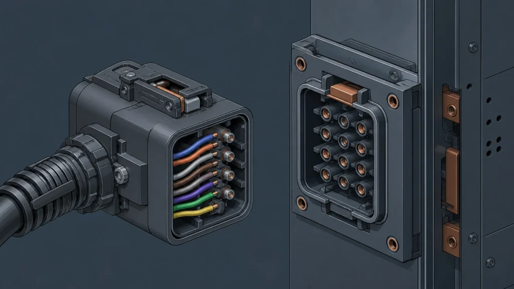
A physically compatible secondary plug connector does not guarantee that pin assignments match the circuit-breaker's internal wiring. The housing geometry confirms only the mechanical interface; the secondary plug connector pinout — which pin carries which control, auxiliary, or signaling function — is determined by the breaker's internal wiring diagram, its installed optional features, and the specific equipment revision. Proceeding on the assumption that identical housings mean identical pinouts is one of the most common sources of misoperation, nuisance tripping, and protection-scheme failure in secondary connectors and control components.
The Core Problem: Housing Fit vs. Electrical Function
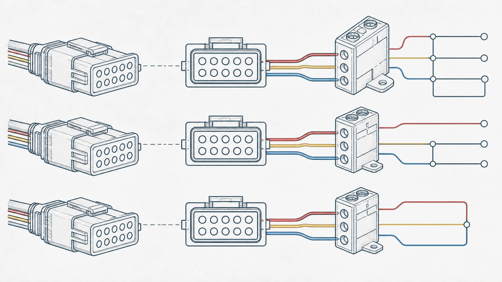
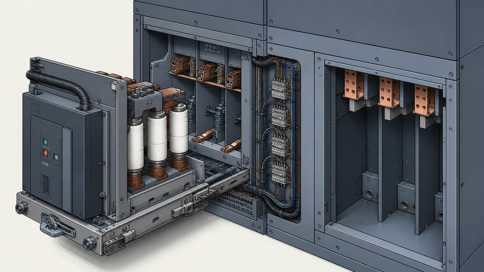
Secondary connectors on withdrawable medium-voltage circuit breakers serve a dual purpose. Mechanically, they create a reliable separable interface between the breaker's internal circuits and the switchgear cubicle's control wiring. Electrically, they carry every signal the breaker needs to operate: close and trip coils, auxiliary switch contacts, motor-supply circuits, alarm outputs, interlocks, and — on modern designs — communication bus connections.
The housing form factor is standardized within a breaker family so that any breaker of that frame size can physically engage the cubicle's mating connector. This standardization is intentional: it allows breakers to be racked in and out without custom mechanical adapters. But physical standardization says nothing about what appears on each pin. Two breakers of the same frame size, from the same manufacturer, built five years apart or ordered with different optional features, can present entirely different signals on the same pin number.
ABB's documented internal-wiring diagram for the SecoVac vacuum circuit-breaker illustrates this directly. The diagram maps each secondary pin number to a specific circuit function — close coil, trip coil, auxiliary contacts, motor supply, and so on — and the mapping changes depending on which optional features (second trip coil, spring-discharge contact, additional auxiliary switches, anti-pumping relay configuration) are installed. The only reliable way to know what a given pin carries is to check the exact diagram for the exact breaker revision. A matching housing is necessary for connection; it is not evidence of electrical compatibility.
Why Pin Assignments Vary Within a Single Breaker Family
Several factors cause pinout variation even when the connector housing is identical.
**Optional features change pin allocation.** A breaker ordered with a single trip coil uses fewer pins for tripping than one ordered with two independent trip coils. The freed pins may be reassigned to auxiliary contacts, alarm outputs, or left unconnected. A procurement team replacing a single-trip-coil breaker with a dual-trip-coil variant — or vice versa — must verify every pin, not just the ones they expect to differ.
**Auxiliary switch configurations vary.** The number and type (NO/NC) of auxiliary contacts, and their mapping onto secondary connector pins, depend on the ordered configuration. Two breakers of the same model with different auxiliary-switch arrangements will present different signals on overlapping pin positions.
**Revision-level changes.** Manufacturers periodically revise internal wiring to accommodate component changes, regulatory updates, or design improvements. A breaker manufactured in 2018 may not share the same pinout as one manufactured in 2023, even if the catalog number appears similar. The internal-wiring diagram shipped with each unit is the controlling document.
**Motor and heater circuits.** Spring-charging motor supply, anti-condensation heater circuits, and their associated supervision contacts occupy secondary pins. Whether these are present, and where they appear, depends on the breaker's ordered scope of supply.
What IEC 62271-100 Does and Does Not Establish
IEC 62271-100 is a product standard for alternating-current circuit-breakers above 1 kV. It defines performance requirements — making and breaking capacities, dielectric withstand, mechanical endurance, and type-test protocols — that a compliant breaker must satisfy.
The standard establishes the functional scope of what a medium-voltage circuit breaker must do. It does not prescribe a universal secondary-connector pinout. Connector geometry, pin count, and pin assignment remain manufacturer- and model-specific design choices. Citing IEC 62271-100 compliance on two breakers confirms that both meet the same performance envelope. It does not confirm that their secondary connectors are electrically interchangeable.
This distinction matters at the procurement stage. When specifying a replacement vacuum circuit breaker, an IEC 62271-100 reference number on the datasheet confirms the breaker's ratings and test basis. It does not eliminate the need to compare secondary-connector pinouts pin by pin against the cubicle's existing wiring.
A Pin-by-Pin Verification Workflow
Before any replacement or spare-breaker decision, the following evidence should be assembled. This is an identification and documentation exercise, not an authorization to modify field wiring.
**Step 1 — Obtain the internal-wiring diagram for the existing breaker.** This is the as-built diagram shipped with the original breaker or available from the manufacturer by serial number. Do not rely on a generic catalog diagram; it may not reflect the options actually installed.
**Step 2 — Obtain the internal-wiring diagram for the proposed replacement.** Request the diagram for the specific revision and option configuration being quoted. Confirm the diagram revision date matches the production batch.
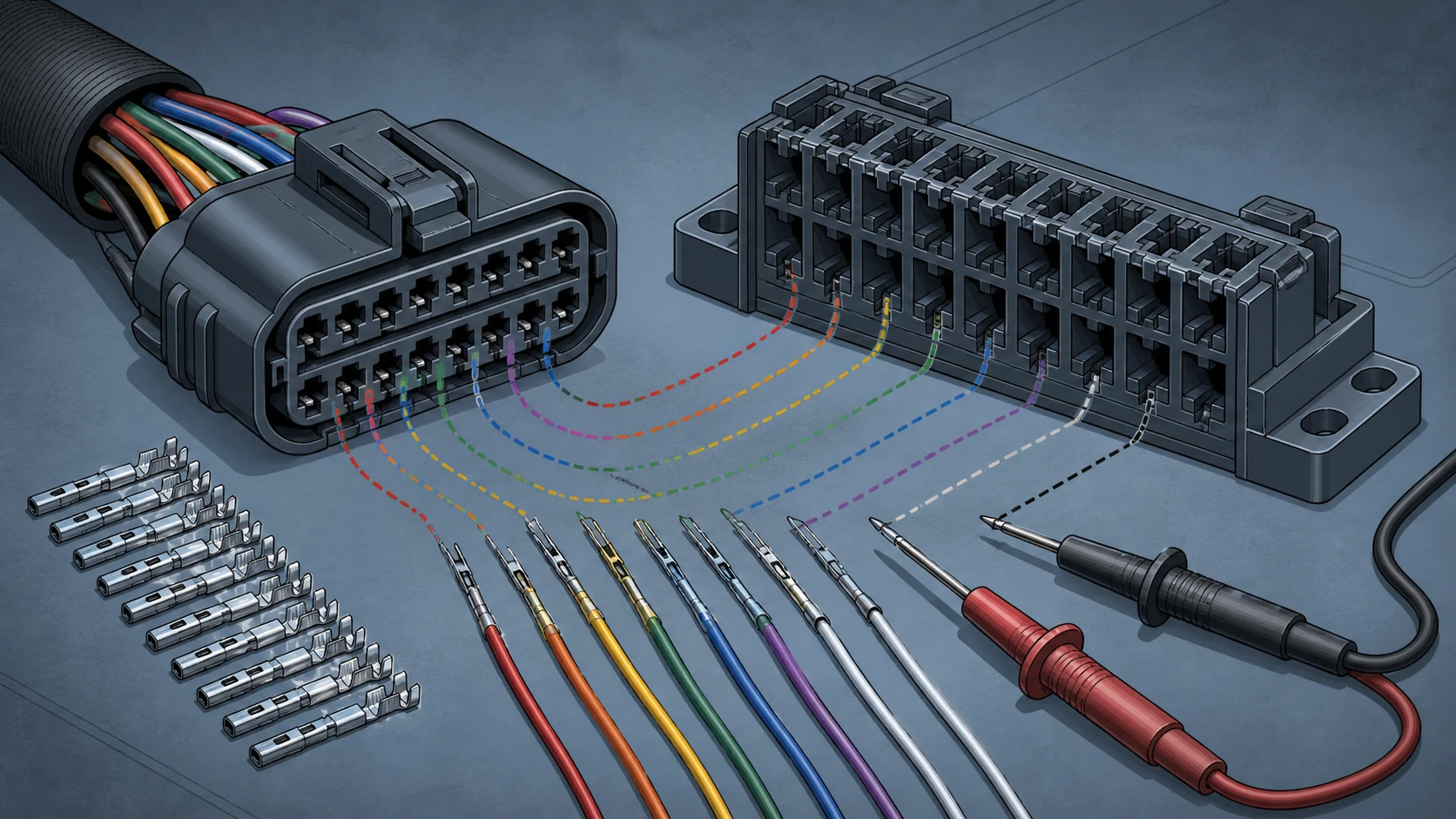
**Step 3 — Map each pin function side by side.** For every pin on the secondary connector, record the circuit function from each diagram. Flag any pin where the function differs, the signal polarity differs, or one diagram shows "not connected" while the other shows an active circuit.
**Step 4 — Identify cubicle-side wiring dependencies.** The switchgear cubicle's control scheme expects specific signals on specific pins. Any pinout mismatch means either the cubicle wiring or the breaker wiring must be reconciled — a scope item that requires engineering review, not a field improvisation.
**Step 5 — Document and escalate discrepancies.** Any mismatch found in Step 3 or Step 4 should be documented and referred to the switchgear OEM, the breaker manufacturer, or a qualified engineering authority for resolution. Model-specific approved procedures govern any wiring changes.
Common Mismatch Scenarios and Their Consequences
| Mismatch Type | What Happens | How It Is Caught |
|---|---|---|
| Trip coil on wrong pin | Breaker fails to trip on protection command, or trips on an unrelated signal | Pin-by-pin diagram comparison before installation |
| Auxiliary contact NO/NC reversal | Protection relay receives inverted breaker-position feedback; scheme logic fails | Comparing auxiliary-switch configuration codes and pin mapping |
| Motor supply on signal pin | Spring-charging motor voltage appears on a low-level signal circuit; damage to relay inputs | Checking motor-circuit pin allocation against cubicle termination schedule |
| Missing second trip coil circuit | Redundant protection path is open; single-contingency trip capability lost | Verifying option codes and pin count against protection scheme requirements |
| Heater circuit on different pins | Anti-condensation heater inactive or energized through unintended path | Cross-referencing heater pin assignment with cubicle heater supply wiring |
None of these faults is detectable by confirming that the plug fits the socket. Every one requires diagram-level verification.
What to Assemble Before an RFQ or Replacement Decision
Procurement and engineering teams should gather the following data before requesting a quotation for a replacement or spare secondary connector assembly, or for a replacement breaker that must interface with existing cubicle wiring. Use the secondary-plug replacement checklist as the identification baseline.
- **Existing breaker serial number and revision.** This allows the manufacturer to retrieve the exact as-built wiring diagram.
- **Existing breaker option code string.** The option codes define which features (trip coils, auxiliary switches, motor, heater, communication) are present and how they are wired.
- **Cubicle secondary-connector termination schedule.** The cubicle-side document that records which wire lands on which pin of the mating connector.
- **Protection and control scheme drawings.** These show what signal the cubicle expects on each pin and how the breaker interfaces with relays, interlocks, and SCADA.
- **Target breaker catalog number and option codes.** The proposed replacement must be quoted with the same level of option detail so the manufacturer can supply the correct wiring diagram for comparison.
With these five documents in hand, a pin-by-pin comparison can proceed on paper before any hardware is ordered. Discovering a pinout mismatch after delivery — or worse, after installation — introduces delay, rework cost, and risk.
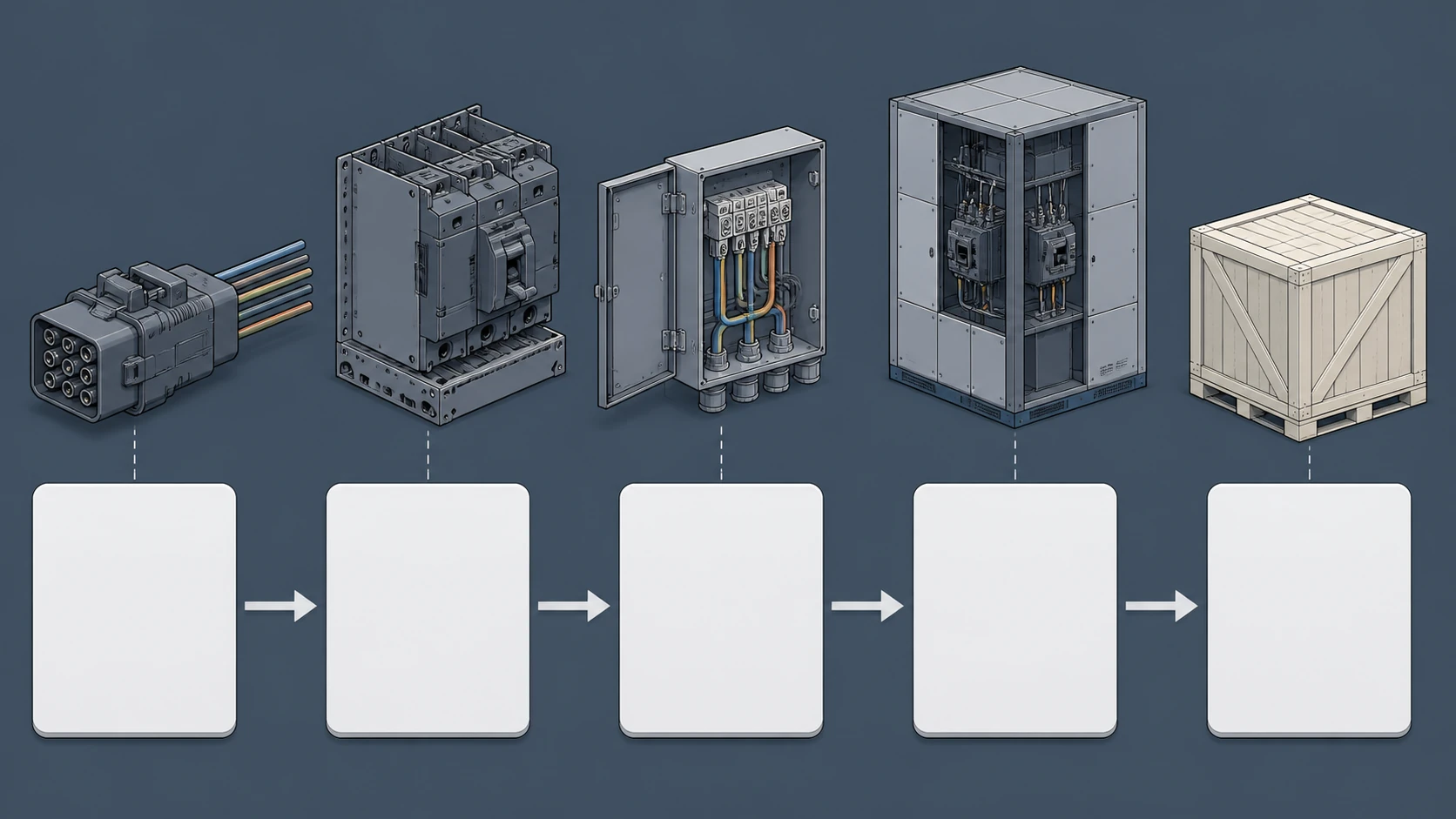
When a Secondary Connector Assembly Itself Needs Replacement
Separate from the breaker-replacement scenario, the secondary connector housing or contact assembly itself may require replacement due to wear, heat damage, or contact degradation. Even in this case, a physically identical housing is only the starting point. The replacement assembly must be verified against the breaker's internal-wiring diagram to confirm that contact positions, current ratings, and any keying features match the installed configuration. Connector assemblies from the same manufacturer but different production periods may have different contact-retention mechanisms, plating specifications, or pin-count options that are not visible from the housing exterior; the cubicle interface also belongs in the MV switchgear components review.
Reeuini supplies secondary connectors and control components matched to specific breaker families and configurations. Specifying by breaker serial number and option code, rather than by housing appearance alone, is the most reliable path to a correct replacement.
FAQ
What is a secondary plug connector pinout?
A secondary plug connector pinout is the documented mapping between each pin number on a circuit breaker's secondary (control) connector and the specific electrical function that pin carries — such as trip coil, close coil, auxiliary contact, motor supply, or alarm output. The pinout is defined by the breaker's internal-wiring diagram and varies with the breaker's installed options and revision level.
What is the risk of assuming two connectors with the same housing are interchangeable?
The risk is that control signals land on the wrong circuits. Consequences range from a breaker that fails to trip on a protection command, to a breaker that trips spuriously, to relay-input damage from motor-supply voltage appearing on a signal pin. The housing confirms only the mechanical interface. Electrical compatibility requires a pin-by-pin diagram comparison.
What is the role of IEC 62271-100 in confirming pinout compatibility?
IEC 62271-100 defines performance and test requirements for AC circuit breakers above 1 kV. It does not prescribe secondary-connector pinouts. Two breakers that both comply with IEC 62271-100 may have entirely different pin assignments. The standard confirms the breaker's ratings and type-test basis, not its connector wiring.
What is the minimum documentation needed to verify a secondary connector pinout before ordering a replacement?
At minimum, the existing breaker's serial number, option codes, and as-built internal-wiring diagram; the cubicle's secondary-connector termination schedule; and the proposed replacement's catalog number, option codes, and wiring diagram. These documents allow a pin-by-pin comparison on paper before any hardware is procured or installed.
What is the correct action when a pinout mismatch is found between an existing and proposed breaker?
Document the specific mismatched pins and their respective functions, then escalate to the switchgear OEM, the breaker manufacturer, or a qualified engineering authority. Do not attempt to reconcile the mismatch by re-terminating wires in the field without an approved engineering change. Model-specific approved procedures govern any wiring modifications.

