

Quick Takeaway
- Confirm the project duty and applicable requirements for Conductive Components before selection or service work.
- Use recorded inspection and test evidence instead of unsupported assumptions.
- Keep the final acceptance, maintenance, and handover documents with the equipment record.
When specifying or replacing conductive components in switchgear assemblies, you need documented temperature-rise evidence before you can evaluate whether a component will perform reliably at its rated current. That evidence is not a single number on a datasheet — it is a set of test records, boundary conditions, and material declarations that together let you judge thermal margin in the MV Switching Equipment context. This article explains what to request from the design team and how to read what comes back.
Why Temperature-Rise Evidence Matters for Conductive Components
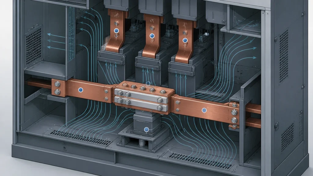
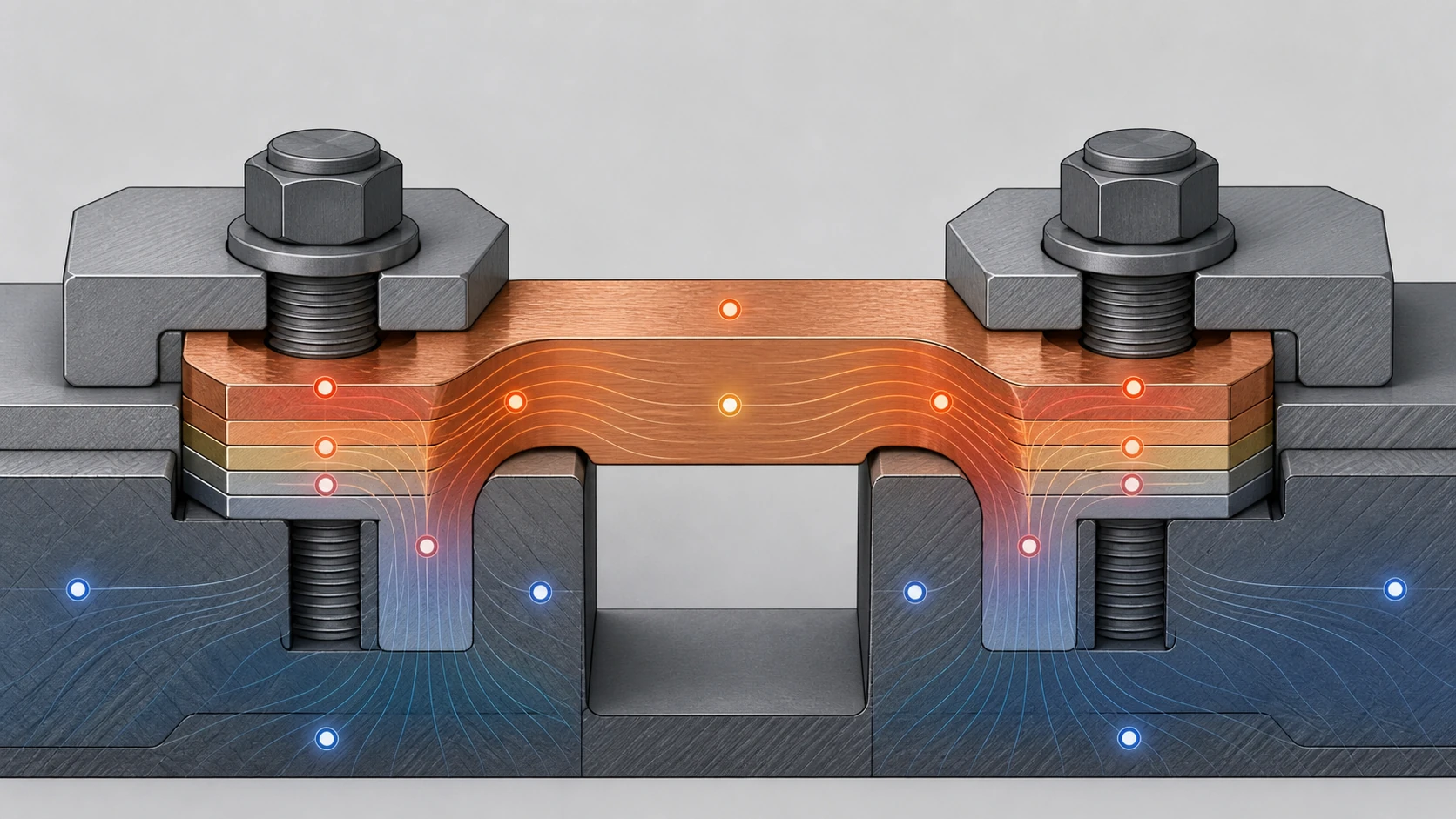
A conductive component — a contact arm, a terminal connector, a current-carrying bridge — converts a small fraction of the current it carries into heat through resistive losses. The temperature that results depends on the component's bulk resistivity, contact resistance at each interface, cross-sectional geometry, surface emissivity, and the thermal path to ambient air or adjacent metalwork. A component that meets its current rating at 20 °C ambient inside a spacious test enclosure may exceed allowable temperature limits when installed in a densely packed switchgear compartment with restricted airflow and adjacent heat sources.
Temperature-rise evidence closes that gap. It tells you the conditions under which the component was tested, what temperatures were recorded, and what stop criteria governed the test. Without it, you are relying on a catalog rating that may not reflect your installation reality. ABB's description of temperature-rise testing for switchgear and switching devices under continuous current confirms that valid thermal evaluation includes monitored currents and temperatures alongside predefined stop conditions — the test setup and the recorded conditions are both part of the evidence package, not just the final pass/fail result.
The practical consequence for procurement and design teams: request the evidence package early, read beyond the summary, and match its boundary conditions against your actual installation before locking in a component selection.
The Boundary Between Evidence Review and Compliance Certification
This article helps you formulate the right questions and interpret the evidence you receive. It does not calculate temperature rise for a specific component, and it does not certify compliance with any standard. That determination belongs to the design authority, the test laboratory, and the certification body.
IEC 62271-1 applies to AC high-voltage switchgear and controlgear and includes temperature-rise provisions as part of its common specifications. The standard defines allowable temperature rises for contacts, connections, and accessible surfaces based on material class and plating type. Citing IEC 62271-1 here provides standard-scope context only; it does not determine compliance for any product. Your design team should confirm which edition and national annex apply, and whether the conductive component in question falls within the scope of that standard or under a different one entirely.
Keep that boundary clear when formulating your requests. You are asking the design team to show you evidence; you are not auditing or certifying it yourself.
What a Complete Temperature-Rise Evidence Package Contains
A useful evidence package for a conductive component goes beyond a single test report summary. The following elements, taken together, let you evaluate whether the evidence is relevant to your application.
**Test current and duration.** The report should state the continuous current applied during the test and the duration or the thermal-stabilization criterion that defined when the test ended. ABB's high-current testing methodology includes predefined stop conditions — typically a requirement that temperature rise does not exceed a specified rate of change over a defined period. If the report only states "tested at rated current" without specifying the actual amperage and stop criterion, the evidence is incomplete.
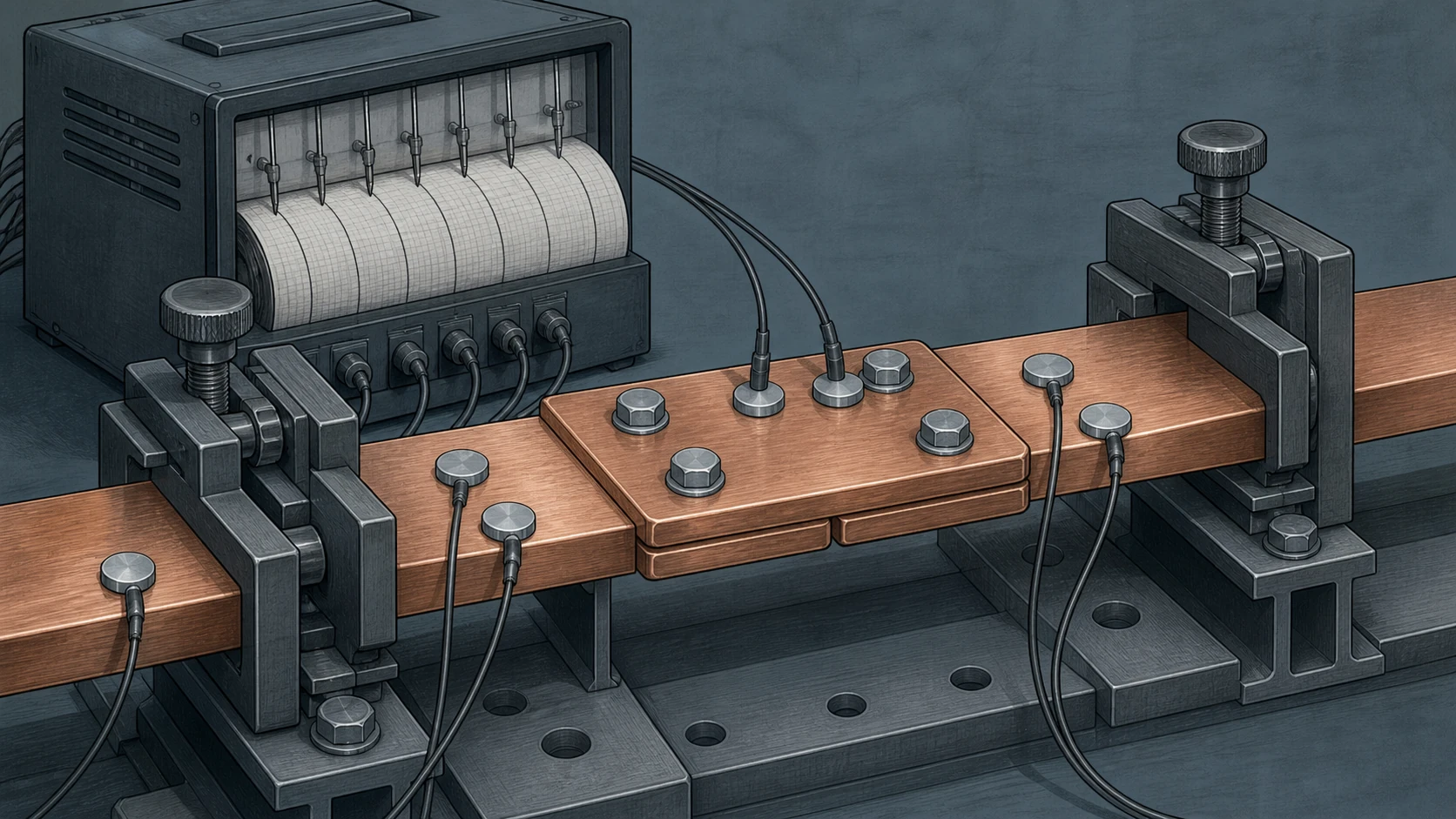
**Thermocouple locations.** Temperature was measured somewhere. You need to know where. A thermocouple on the body of the component, one on each terminal interface, and one measuring ambient temperature inside the test enclosure represent a minimum useful set. If only one measurement point is documented, you cannot distinguish between bulk heating and localized hot spots at contact interfaces.
**Ambient and enclosure conditions.** The temperature-rise value is the difference between the component temperature and the reference ambient. If ambient was measured outside the test enclosure rather than inside it, or if the enclosure geometry does not resemble your switchgear compartment, the rise value may understate what you will see in service.
**Contact resistance or millivolt-drop data.** For bolted or plug-in interfaces, initial and final resistance measurements across the joint bracket the condition of the contact. A significant increase in resistance during the test suggests surface degradation that would worsen over the component's service life.
**Material and plating declarations.** Allowable temperature-rise limits vary by material class. Silver-plated contacts have different limits than tin-plated or bare copper contacts under IEC 62271-1. The evidence package must identify the plating and substrate so you can check it against the correct limit column.
**Photographs or diagrams of the test setup.** These let you judge whether the mounting orientation, conductor routing, and ventilation conditions during the test are representative of your intended installation.
Questions to Ask the Design Team Before Requesting Evidence
Before you ask for the report itself, establish context with these questions. They help you determine whether the evidence that exists is even relevant to your application.
The first question is scope: at what continuous current was the component tested, and does that current match your application's maximum continuous rating? A component tested at 2000 A does not automatically qualify at 2500 A, even if its catalog rating says 2500 A, unless the test was conducted at that higher value or a validated derating methodology was applied.
The second question is configuration: was the component tested in isolation, or was it tested as part of an assembly? A conductive component mounted between two busbars inside a sealed compartment behaves differently than the same component tested on an open bench with free-air convection. If the test was done in isolation, ask what correction or margin the design team applies to account for the installed thermal environment.
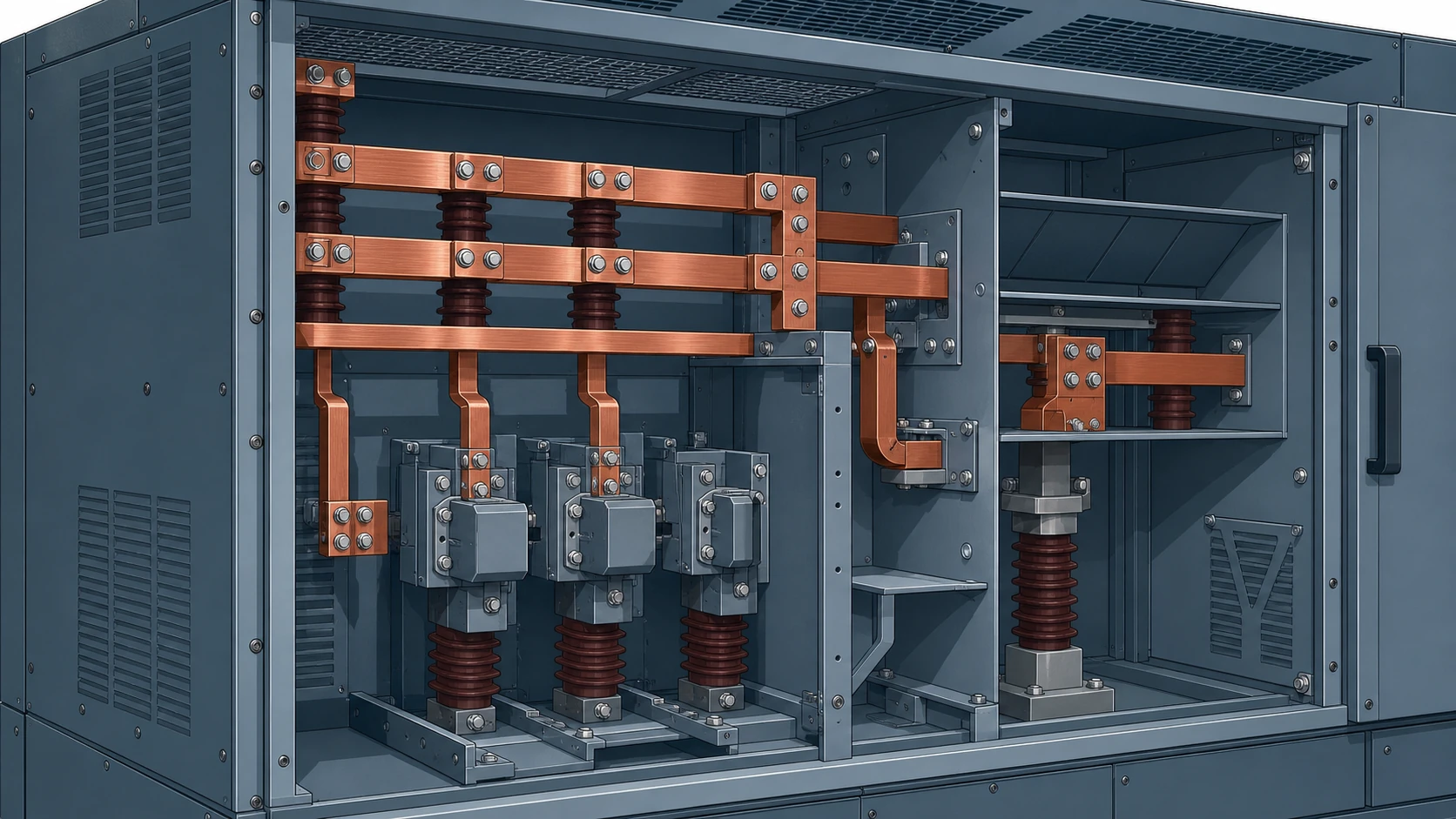
The third question is interface dependency: what torque values, contact pressure, or engagement depth were used during the test, and are those values documented in the installation procedure for your assembly? Temperature rise at a bolted joint is sensitive to bolt torque. Temperature rise at a plug-in contact is sensitive to spring force and plating condition. If the test conditions assumed a specific torque or engagement and your assembly procedure specifies a different value, the evidence may not transfer; review the interface in the relevant MV switchgear components record.
The fourth question is age and revision: does the evidence apply to the current manufacturing revision of the component? Material sourcing changes, plating thickness tolerances, and minor geometry revisions can all affect resistive losses. Confirm that the test report revision aligns with the component revision you are purchasing.
How to Read and Compare Temperature-Rise Data Across Suppliers
When you receive evidence packages from multiple conductive component suppliers, direct comparison is only valid if the boundary conditions match. The table below highlights the parameters that must align before you can meaningfully compare two temperature-rise values.
| Parameter | What to check | Risk if mismatched |
|---|---|---|
| Test current | Identical amperage or clearly stated derating basis | Lower test current produces artificially favorable rise values |
| Ambient reference | Both measured at the same location relative to the component | Different ambient reference points shift the reported rise |
| Stabilization criterion | Same rate-of-change threshold and measurement interval | A shorter or looser criterion may end the test before true stabilization |
| Enclosure conditions | Similar geometry, ventilation, and adjacent heat load | Open-air results understate rise in a confined compartment |
| Contact interface | Same plating, torque, and mating configuration | Different interface conditions change the dominant heat source |
If the boundary conditions do not match, do not compare the final temperature-rise numbers directly. Instead, ask each supplier to restate their results against a common set of conditions, or ask the design team to normalize the data with documented assumptions.
Installation, Inspection, and Commissioning Considerations
Temperature-rise evidence informs the selection decision, but the thermal performance you achieve in service depends on correct installation. Model-specific approved procedures govern torque sequences, contact-pressure verification, conductor termination methods, and any post-installation thermal checks. This article does not provide those procedures. For a replacement request, start with the conductive-parts interface-data checklist and confirm adjacent insulation components separately.
What the evidence review does tell you about installation risk:
If the evidence package shows that temperature rise is sensitive to contact resistance at the interface — which it almost always is for bolted or plug-in connections — then any deviation from the specified torque, surface preparation, or engagement depth during installation will degrade the thermal performance below what the test demonstrated. Flag this to the installation team explicitly.
If the evidence package was generated under open-air or bench conditions and your switchgear compartment restricts airflow, request that the design team specify an installation derating or a maximum allowable ambient temperature inside the compartment. Without that, you have no documented basis for the thermal margin in your actual enclosure.
Commissioning-stage thermal imaging, where the assembly is energized at rated current and an infrared survey is performed, provides field confirmation that the installed temperature rise is consistent with the evidence. It does not replace the laboratory evidence, but it closes the loop between tested and installed performance.
Building the Evidence Request Into Your RFQ
Temperature-rise evidence is easiest to obtain when it is requested as a deliverable at the RFQ stage, not after the purchase order is issued. Include the following in your technical requirements or data-request schedule:
State the specific continuous current at which you need evidence, not just the catalog rating. If your application requires 3150 A, ask for evidence at 3150 A.
Require that the evidence package include thermocouple locations, ambient reference method, stabilization criterion, and contact-resistance measurements. Generic statements like "temperature rise within limits" are not actionable.
Specify the applicable standard edition and clause. If IEC 62271-1 governs your assembly, reference the edition and national annex so the supplier's evidence can be checked against the correct allowable-rise table.
Request material and plating declarations as part of the evidence, not as a separate quality document. The plating type determines which temperature-rise limit applies, so decoupling these documents creates a verification gap.
Ask whether the evidence was generated by the component manufacturer's own laboratory or by a third-party test house. Both can be valid, but third-party evidence may carry more weight in some regulatory or utility-approval contexts.
If you are evaluating conductive components from multiple suppliers, standardize your evidence request so the responses are comparable. A common data-request template eliminates the normalization problem described in the comparison section above.
FAQ
What is temperature-rise evidence for a conductive component?
Temperature-rise evidence is a documented set of test records showing the temperature a conductive component reaches under a specified continuous current, including the test setup, thermocouple locations, ambient reference, stabilization criteria, and material declarations. It goes beyond a single pass/fail statement to provide the boundary conditions needed to judge whether the tested performance applies to a specific installation.
What is the role of IEC 62271-1 in temperature-rise evaluation?
IEC 62271-1 provides common specifications for AC high-voltage switchgear and controlgear, including temperature-rise provisions that define allowable limits based on material class and plating type. It sets the framework within which temperature-rise testing is conducted and results are evaluated. The applicable edition and national annex must be confirmed by the design authority for each specific product and application.
What is the difference between a catalog current rating and temperature-rise evidence?
A catalog current rating is a summary specification that states the maximum continuous current a component is designed to carry. Temperature-rise evidence is the underlying test data proving that the component meets allowable temperature limits at that current under specific, documented conditions. The rating alone does not tell you whether those conditions match your installation, which is why the evidence package is necessary.
What is the most common gap in temperature-rise evidence packages?
The most common gap is missing or inadequately documented boundary conditions — particularly the ambient reference location, enclosure geometry, and contact-interface preparation used during the test. Without these, the temperature-rise number itself cannot be meaningfully evaluated against your actual application. When reviewing evidence, check for these details first; their absence is a stronger warning signal than a marginally high temperature-rise value.
What is the best time to request temperature-rise evidence from a supplier?
The best time is at the RFQ stage. Including the evidence request in your technical requirements ensures the supplier responds with documented test data as part of the commercial process, before component selection is locked. Requesting evidence after a purchase order is issued often results in delays and generic documentation that lacks the boundary-condition detail needed for a proper review.

