

Quick Takeaway
- Confirm the project duty and applicable requirements for Disconnect Switches before selection or service work.
- Use recorded inspection and test evidence instead of unsupported assumptions.
- Keep the final acceptance, maintenance, and handover documents with the equipment record.
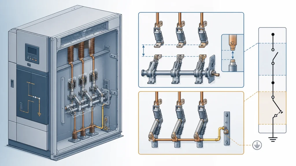
A disconnect switch creates a visible isolation gap so personnel can confirm a circuit is de-energized before work begins. An earthing switch bonds the isolated conductor to ground, draining trapped charge and blocking re-energization from any source. These two functions protect against different hazards at different moments in a switching sequence, and combining or confusing them introduces risks that neither device can compensate for alone. Preserve the distinction in the Disconnect Switches selection context.
| Decision factor | Disconnect switch | Earthing switch |
|---|---|---|
| Primary function | Provides a visible open gap for isolation | Connects isolated conductor to earth potential |
| When it operates | After load-break device opens the circuit | After disconnect switch confirms visible isolation |
| What it protects against | Unintended re-energization from the supply side | Residual charge, induced voltage, back-feed from distributed sources |
| Rated duty | Carries and interrupts no-load or residual current within its rating; not designed to break fault or load current | Closes onto a potentially charged conductor; rated for short-circuit making current in maintenance earthing applications |
| Typical interlock relationship | Must be confirmed open before earthing switch can close | Must be confirmed open (earthed removed) before disconnect switch can close |
| Governing standard scope | IEC 62271-102, which covers alternating-current disconnectors and earthing switches as distinct device categories | IEC 62271-102, same standard, separate performance and test clauses |
Why the Functional Boundary Exists
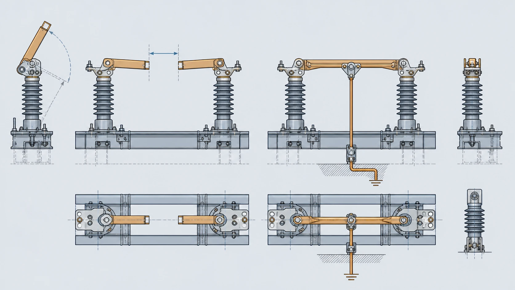
The disconnect switch and the earthing switch occupy adjacent but non-overlapping positions in an isolation sequence. A disconnect switch proves the gap. An earthing switch proves the ground path. Removing either step leaves a category of hazard unaddressed.
A disconnect switch, once open, gives a visual or mechanical confirmation that the primary conductor is physically separated from the energized bus. This visible gap is the foundational safety evidence in any isolation procedure. But an open disconnect switch alone does not guarantee zero voltage on the downstream conductor. Capacitive coupling, inductive coupling from parallel circuits, and back-feed through transformers or distributed generation can all sustain hazardous potential on a conductor that appears isolated.
The earthing switch addresses exactly that residual hazard. By bonding the isolated conductor to the station ground grid, it collapses any trapped or induced voltage to earth potential. It also provides a solid fault path: if any source re-energizes the conductor while personnel are working, the earthing switch forces a fault that upstream protection can detect and clear. No disconnect switch is designed or rated for that duty.
ABB presents disconnectors and earthing switches as separate switch types in high-voltage switchgear, reinforcing the principle that each device fulfills a distinct protective role. This separation is not a legacy convention. It reflects the reality that the electrical hazards at each stage of isolation are fundamentally different in character and demand different device ratings.
Electrical and Mechanical Differences That Drive Separation
The ratings, contact design, and operating mechanisms of the two switches diverge because they manage different energy conditions.
A disconnect switch is rated to carry continuous current and to interrupt only the small currents present under no-load conditions—bus-transfer currents, charging currents of short cable lengths, and magnetizing currents within its specified limits. Its contacts are optimized for low-resistance current-carrying and for providing a clear, inspectable gap when open. The operating mechanism must hold the contacts firmly in either the closed or the open position, and many designs include a mechanical flag or window to confirm position from a distance.
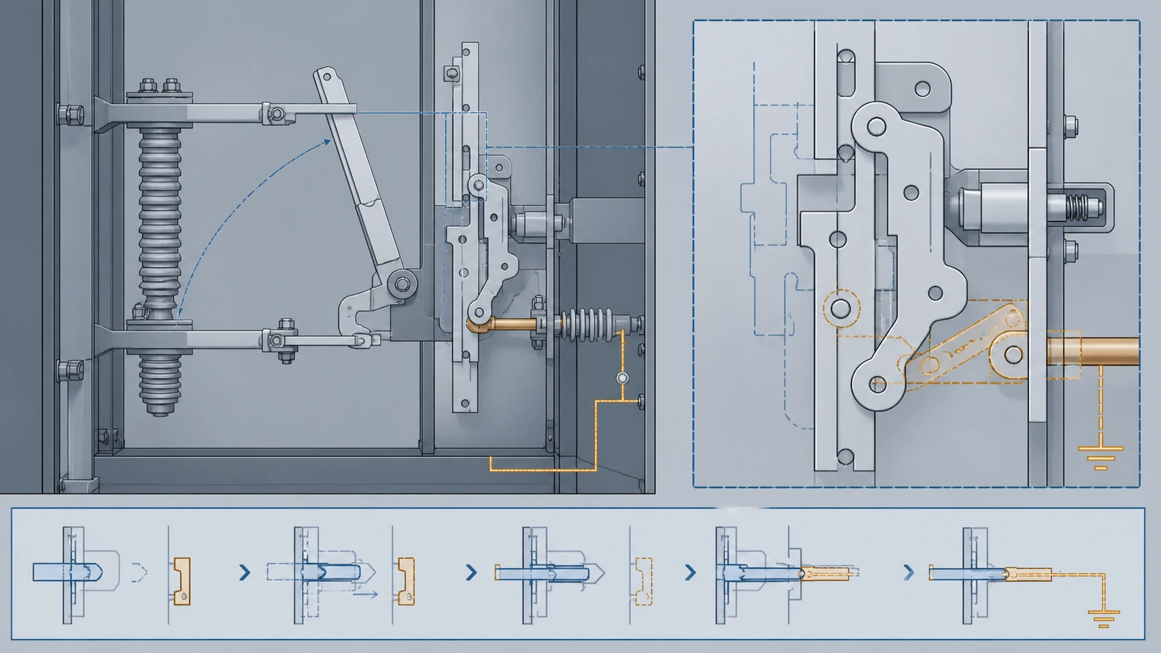
An earthing switch, by contrast, must be capable of closing onto a conductor that may still be energized due to an error in the switching sequence or an unforeseen back-feed. Its critical rating is the short-circuit making capacity: the peak current it can safely conduct during the asymmetric first half-cycle of a fault. The contacts and drive mechanism are built for high closing force and rapid engagement rather than for continuous current-carrying efficiency. In many designs the earthing switch blade is lighter than the main disconnect blade because it does not carry load current during normal service. Its open position simply parks the blade away from the conductor; it does not need to provide the visible isolation gap that defines a disconnect switch.
These mechanical differences are why a single device cannot reliably serve both purposes. A disconnect switch contact designed for visible gap assurance and steady-state current does not have the making-current rating required for a safe earthing closure. An earthing switch contact designed for high-impact fault-making closure does not provide the stable, low-resistance joint needed for years of continuous load-current service.
Interlock Logic and the Sequence It Enforces
Interlocks between disconnect switches and earthing switches exist to enforce the correct operational sequence and to prevent physically incompatible states. The fundamental rule is straightforward: the earthing switch must not close until the disconnect switch is confirmed open, and the disconnect switch must not close until the earthing switch is confirmed open.
This sequence prevents two specific failure modes. Closing an earthing switch while the disconnect switch is still closed would short the live bus directly to earth through the earthing switch, creating a bolted phase-to-ground fault at full system fault level. Closing the disconnect switch while the earthing switch is still engaged would energize a grounded conductor, again producing a bolted fault and potentially destroying both devices along with adjacent equipment.
Interlock implementation varies by switchgear design: mechanical key-exchange systems, mechanical lever interlocks, electrically supervised solenoid locks, and programmable logic in modern digital substations all serve the same logical purpose. The specific interlock scheme for any given installation is defined by the switchgear manufacturer's documentation and the station operating procedures. This article identifies the interlock boundary that must exist; the model-specific approved procedures govern the implementation, testing, and override policy of that interlock.
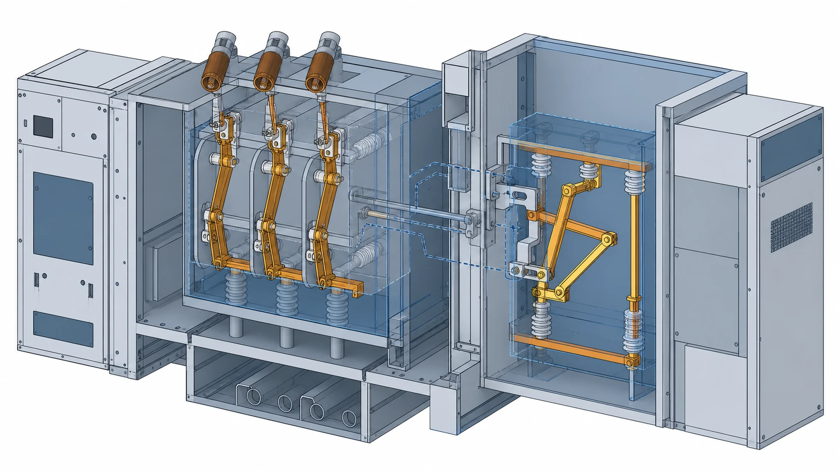
One decision-relevant point for procurement and specification: when evaluating disconnect switches and earthing switches from different manufacturers or across different equipment generations, verify that the interlock interface is mechanically and electrically compatible. A disconnect switch and earthing switch that are each individually compliant with IEC 62271-102 may still lack a proven interlock interface if they were not designed as a coordinated pair. The interlock compatibility question should appear on every RFQ and every replacement evaluation of MV Switching Equipment.
Standards Scope and Evidence Boundaries
IEC 62271-102 covers high-voltage alternating-current disconnectors and earthing switches within a single standard, but it defines separate performance requirements, test sequences, and rating categories for each device type. The standard treats them as distinct apparatus that happen to share a physical switchgear compartment and an operational sequence.
For disconnect switches, the standard addresses rated normal current, rated short-time withstand current, rated peak withstand current, dielectric withstand across the isolating distance, and the mechanical endurance of the operating mechanism. For earthing switches, it addresses rated short-circuit making current, short-time withstand, and the specific test duty that proves the earthing switch can close safely onto a faulted or charged conductor.
This standard scope is referenced here to establish the functional and testing boundary between the two devices. It is not used as an operating instruction, a model-specific approval, or a substitute for project-specific engineering analysis. Any claim about a particular switch's compliance with IEC 62271-102 should be supported by the manufacturer's type-test report for that specific design and rating.
Selection and Verification Workflow Before RFQ
A procurement or replacement decision for disconnect switches, earthing switches, or both requires assembling specific data before issuing a request for quotation. The following workflow consolidates selection, verification, and procurement concerns into a single review sequence.
**System-level data to collect first:**
– Rated voltage, rated normal current, and rated short-circuit current at the installation point. The earthing switch making-current rating must meet or exceed the prospective peak fault current, not just the RMS symmetrical value.
– BIL (basic insulation level) and the required isolating distance withstand voltage for the disconnect switch.
– The interlock scheme in the existing or planned switchgear, including whether the interlock is mechanical, electrical, or both, and whether the new devices must interface with legacy interlock hardware.
– Ambient conditions: altitude, temperature range, pollution level, and whether the installation is indoor or outdoor. These affect creepage distance requirements and may differ between the disconnect switch and the earthing switch if they are mounted in different compartments or on different structures.
**Device-level verification before specification:**
– Confirm that the disconnect switch's rated normal current covers the maximum expected load on the circuit, including any planned capacity additions.
– Confirm that the earthing switch's rated short-circuit making current covers the prospective fault current at the installation point under the worst-case network configuration. If the network is expected to grow, use the projected fault level, not the present value.
– Verify that the manufacturer's type-test report for each device covers the specific ratings and duty class required. A general product brochure is not a substitute for a type-test certificate referencing IEC 62271-102.
– Review the mechanical endurance class. A disconnect switch operated daily in a utility substation has different endurance requirements than one operated a few times per year in an industrial plant.
**Questions to put on the RFQ:**
– Does the quoted disconnect switch include a factory-coordinated earthing switch option, or must the earthing switch be sourced separately? If separate, what is the proven interlock interface?
– What is the rated mechanical endurance in number of operations for each device independently?
– What maintenance intervals does the manufacturer recommend, and what inspection criteria apply to the isolating gap and the earthing contact?
– Are spare contacts and drive components available for the projected service life of the installation?
This workflow is a specification and procurement checklist. Model-specific installation, commissioning, and adjustment procedures are governed by the manufacturer's approved documentation for the selected equipment. The metal-clad switchgear component context helps retain the panel interface record.
Common Failure Patterns When Separation Is Compromised
When the functional boundary between disconnecting and earthing is blurred—by operational shortcut, by equipment degradation, or by misapplication—the consequences cluster around a few predictable failure modes.
**Using a disconnect switch as a de facto earthing path.** In some older or improvised installations, operators have been tempted to close a disconnect switch onto a grounded bus as a substitute for a dedicated earthing switch. The disconnect switch is not rated for short-circuit making duty. If the conductor carries trapped charge or is inadvertently energized, the disconnect switch contacts may weld, fragment, or fail to conduct the fault current safely. The result can range from a stuck switch that cannot be re-opened to an arc-flash event.
**Degraded earthing switch contacts.** An earthing switch that has not been exercised or inspected may develop high contact resistance. When called upon to drain a trapped charge or to conduct fault current, a high-resistance earthing contact dissipates energy as heat at the joint instead of providing a low-impedance path. The earthing switch may appear closed while failing to provide effective grounding. Periodic contact-resistance measurement, at intervals specified in the manufacturer's maintenance documentation, catches this degradation before it matters.
**Interlock bypass without procedural replacement.** Mechanical interlocks wear, keys get lost, and solenoid locks fail. When an interlock is bypassed for maintenance or repair, the operational sequence that prevents cross-energization depends entirely on administrative controls. Every interlock bypass should be temporary, documented, and closed out with a verified restoration of the interlock function. The specific bypass and restoration procedure is governed by station operating rules and the manufacturer's documentation. Start any replacement review with the VCB replacement information checklist.
FAQ
What is the main difference between a disconnect switch and an earthing switch?
A disconnect switch provides a visible gap to isolate a circuit from the energized bus, confirming that the conductor is physically separated from the supply. An earthing switch bonds the isolated conductor to ground potential, draining residual charge and providing a fault path that forces upstream protection to operate if the conductor is re-energized. The disconnect switch proves the gap; the earthing switch proves the ground. Each addresses a hazard the other cannot.
What is the reason a disconnect switch cannot replace an earthing switch?
A disconnect switch is rated for no-load switching duties: bus-transfer currents, line-charging currents, and magnetizing currents within its specified limits. It is not rated for short-circuit making current. If a disconnect switch were closed onto a charged or faulted conductor in an attempt to establish a ground path, the contacts could weld, fragment, or sustain an arc they were never designed to interrupt. An earthing switch is specifically rated and tested under IEC 62271-102 for the making-current duty that this scenario demands.
What is the role of interlocks between disconnect switches and earthing switches?
Interlocks enforce the switching sequence that prevents two dangerous states: earthing a live bus and energizing a grounded conductor. The interlock ensures the earthing switch cannot close until the disconnect switch is verified open, and the disconnect switch cannot close until the earthing switch is verified open. The implementation—mechanical keys, lever locks, electrical supervision, or programmable logic—varies by switchgear design, and the specific scheme is defined by the manufacturer's documentation and station operating procedures.
What is the first data point to verify when specifying an earthing switch for a new or replacement installation?
The prospective peak short-circuit current at the installation point under the worst-case network configuration. The earthing switch must have a rated short-circuit making current that meets or exceeds this value. Using the present-day RMS symmetrical fault current without accounting for the asymmetric peak or future network growth is the most common specification error, because it can leave the earthing switch under-rated for the actual duty it may face.

