

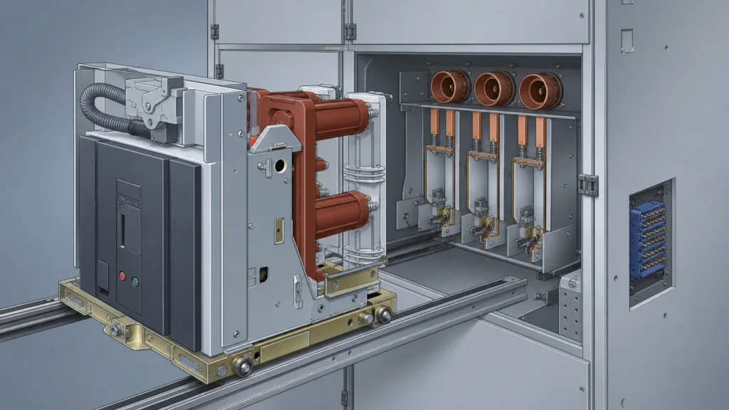
Quick Takeaway
- Confirm the project duty and applicable requirements for Vacuum Circuit Breakers before selection or service work.
- Use recorded inspection and test evidence instead of unsupported assumptions.
- Keep the final acceptance, maintenance, and handover documents with the equipment record.
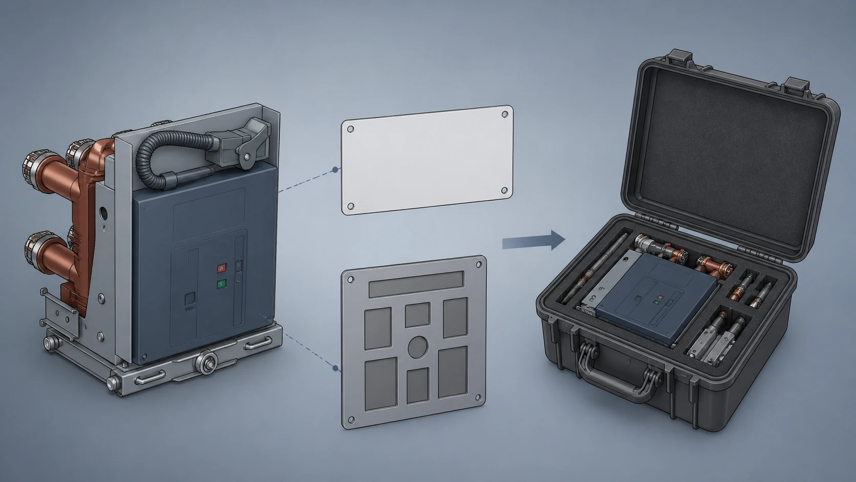
A vacuum circuit breaker nameplate identifies the unit itself; the panel drawing defines the assembly-specific interface that unit must fit. Both must be present and cross-referenced before a replacement review can proceed, but they answer different questions. The nameplate is a retrieval key for the original equipment record, while the panel drawing is the binding evidence that a proposed replacement matches the cubicle's electrical, mechanical, and control-wire configuration.
When only one source is available, or when the two sources conflict, a replacement decision cannot be validated. The rest of this article explains what each document actually proves, where their authority overlaps, and which data points must agree before an RFQ is defensible.
| Criterion | Nameplate | Panel drawing |
|---|---|---|
| Primary function | Equipment identification and document retrieval | Assembly-specific interface definition |
| Typical data carried | Order number, serial number, drawing number, rated voltage, rated current, rated short-circuit breaking current | Bill of material, one-line diagram, control schematics, wiring diagrams, cubicle dimensions, interlock logic |
| What it proves alone | That a specific breaker was manufactured to a catalog specification | That a specific cubicle was designed to receive a breaker with defined interface requirements |
| Limitation | Does not confirm the breaker's installed configuration matches the cubicle it sits in today | Does not confirm the breaker currently installed is the one originally specified |
What the Nameplate Actually Tells You
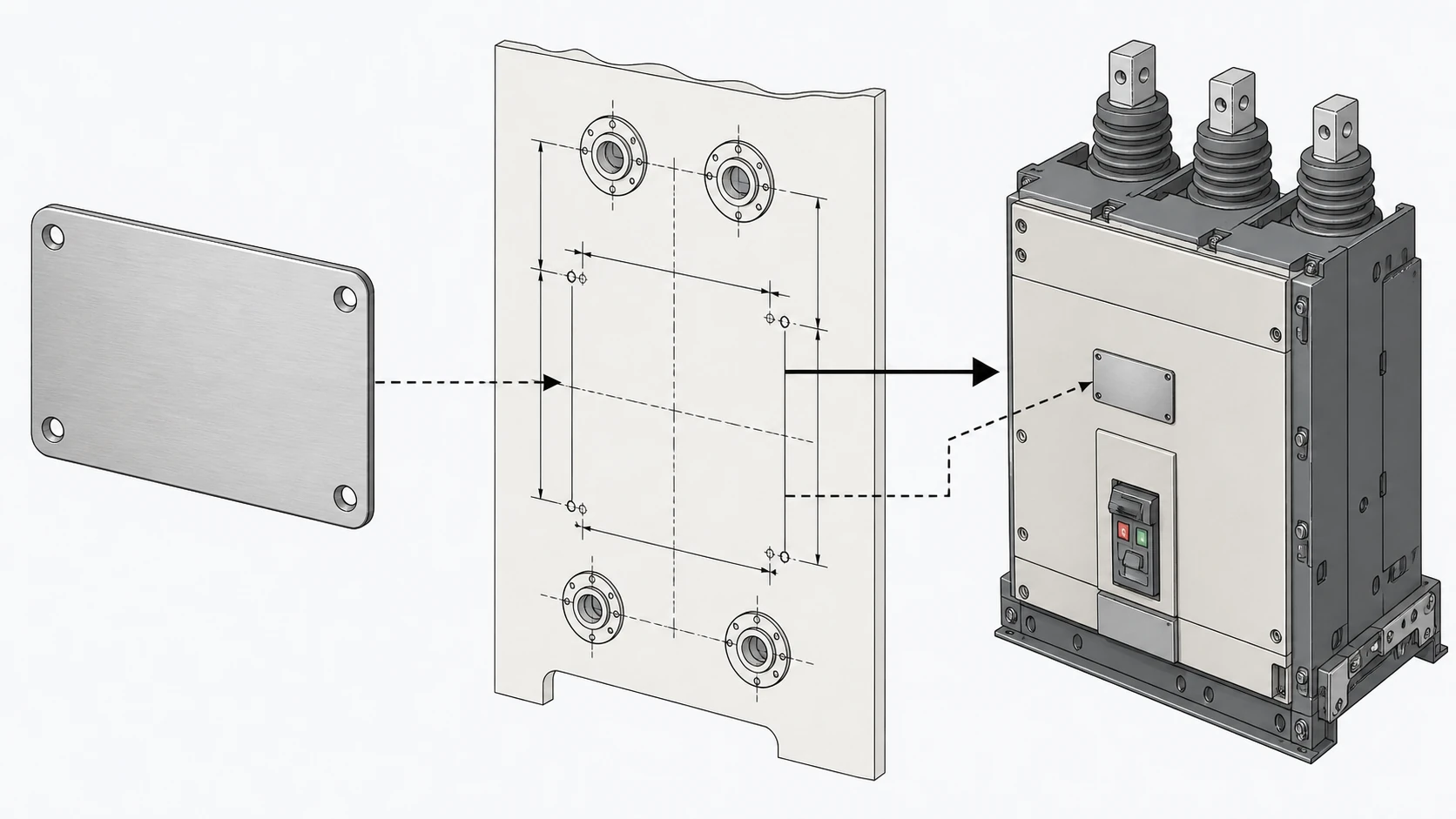
ABB identifies order number, serial number, and drawing number on an equipment nameplate as data to provide when identification of the assembly is required. That phrasing is precise: the nameplate is an identification artifact, not a fitment certificate. It lets the OEM or an aftermarket supplier locate the original manufacturing record, retrieve the factory test report, and confirm catalog-level ratings.
A nameplate typically carries rated voltage, rated normal current, rated short-circuit breaking current, and the applicable standard designation. These values confirm that the breaker was built to handle a particular duty. They do not confirm that the breaker's truck dimensions, spout geometry, auxiliary-contact configuration, or control-circuit termination match the panel it currently occupies. Breakers sharing identical catalog ratings can ship with different truck widths, different CT window sizes, and different secondary plug arrangements depending on the switchgear order.
The practical consequence is clear. A nameplate match on voltage and current ratings between an installed unit and a proposed replacement is necessary but never sufficient. Two breakers rated 12 kV / 1250 A / 25 kA can be mechanically incompatible if they were built against different panel interface drawings.
What the Panel Drawing Actually Tells You
Schneider Electric states that customer-order drawings include bills of material, one-line diagrams, control schematics, and wiring diagrams for a custom-designed switchgear assembly. This body of documentation is the only evidence that ties a breaker specification to a specific cubicle configuration. The panel drawing set captures every interface constraint the breaker must satisfy once it is racked into position: primary spout spacing, secondary plug pinout, shutter interlock clearances, CT ratios, and protection-relay wiring.
A panel drawing is assembly-specific. Two adjacent cubicles in the same lineup can have different breaker ratings, different CT configurations, and different control schemes. The panel drawing for cubicle 3 does not govern cubicle 4, even if both accept the same breaker frame size.
This specificity is why the panel drawing is the binding document. It records not just what the breaker must be, but how the breaker must connect, and what the rest of the cubicle expects from it electrically and mechanically.
The Assembly-Specific Interface Context Under IEC 62271-200
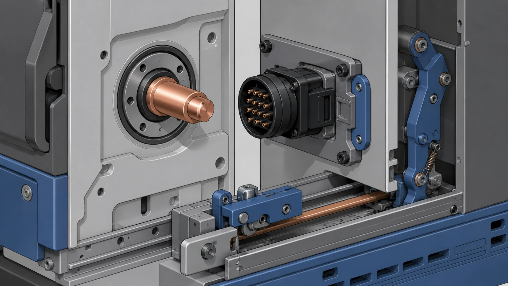
IEC 62271-200 applies to prefabricated AC metal-enclosed switchgear and controlgear assemblies. Within that scope, the circuit breaker and the panel are assessed as an assembly-specific interface context. This means the standard treats the breaker-plus-cubicle combination as a system, not as two independent products that happen to share a compartment. The MV Switching Equipment category supplies wider equipment context, not a fitment decision.
That framing has a direct implication for replacement reviews. A breaker that is type-tested and certified to IEC standards in isolation does not inherit assembly-level compliance when dropped into a cubicle it was not tested with. The internal arc classification, the partition class between compartments, and the degree of protection for the breaker compartment are all properties of the assembly. Changing the breaker changes the assembly; the panel drawing is the document that records what the assembly was designed and verified to be.
An engineering reviewer who skips the panel drawing and relies only on nameplate ratings is effectively assuming the assembly context has not changed. That assumption is defensible only when the replacement is a like-for-like unit from the same OEM order. In every other case, the panel drawing must be consulted.
Where the Two Documents Must Agree
Where a review involves withdrawal, racking, or position signals, the chassis trucks and racking systems category can help name the related interface; it does not establish an interchangeable truck or breaker.
Five categories of data appear in both the nameplate record and the panel drawing. Disagreement in any one of them is a stop condition for the replacement review.
**Rated voltage and insulation level.** The nameplate states the rated voltage. The panel drawing specifies the rated voltage of the assembly and may also specify the rated insulation level. A breaker rated at 12 kV can be offered with different insulation levels depending on system grounding; the panel drawing clarifies which level the cubicle was designed for.
**Rated normal current.** Both documents carry this value, but the panel drawing adds the thermal context: the bus bar cross-section, the connection hardware, and the CT ratio downstream. A breaker with correct rated current but a different primary connection geometry can create a thermal bottleneck the nameplate will not reveal.
**Rated short-circuit breaking current.** The nameplate value must meet or exceed the panel drawing requirement. If the system fault level has been re-studied since original installation, the panel drawing may reference an updated fault-current value that supersedes the nameplate of the unit being replaced.
**Control-circuit voltage and scheme.** The nameplate may note the rated supply voltage for the closing and tripping circuits. The panel drawing defines the full control scheme: which contacts map to which relay inputs, what interlock logic is wired through the secondary plug, and what auxiliary functions (motor-charge confirmation, spring-discharge contact, anti-pump relay) the cubicle expects.
**Mechanical interface identifier.** The nameplate drawing number and the panel drawing's bill of material should reference the same breaker frame or truck designation. If they do not, the records have diverged, and the physical interface cannot be confirmed from documents alone.
When the Documents Conflict or Are Missing
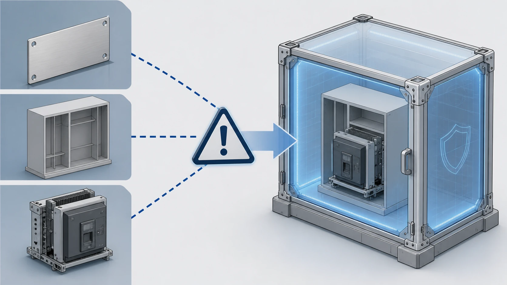
Conflicts fall into two categories: recoverable and non-recoverable at the document level.
A recoverable conflict is one where the discrepancy can be resolved by retrieving an additional record. For example, a nameplate lists a drawing number that does not match the panel drawing's bill of material, but the OEM's order-tracking system confirms a field modification that updated the breaker without updating the panel drawing. The evidence chain is restored once the modification record is located.
A non-recoverable conflict at the document level requires physical verification. If the nameplate is illegible, missing, or replaced with a non-OEM plate, the breaker's identity cannot be confirmed from the nameplate alone. If the panel drawing set was never issued to the site, or was lost, the cubicle's interface constraints are undocumented. In either case, the reviewer must collect physical measurements, secondary-plug pinout data, and interlock geometry from the installed equipment before a replacement can be specified.
Missing documents are not unusual in switchgear that has been in service for decades. Treating a missing panel drawing as equivalent to a generic one is a common procurement error. The absence of a drawing is not evidence that the cubicle is standard; it is evidence that the interface has not been confirmed.
Practical Review Sequence Before an RFQ
The following sequence assumes both documents are available. If either is missing, the sequence pauses at the corresponding step until the gap is closed.
1. Record every field on the installed breaker's nameplate. Photograph the plate; do not transcribe selectively.
2. Retrieve the panel drawing set for the specific cubicle. Confirm the drawing revision matches the as-built condition, including any field-modification records.
3. Cross-reference nameplate rated values against the panel drawing's specified breaker ratings. Flag any value where the nameplate is lower than the drawing requirement.
4. Confirm that the nameplate drawing number or model designation appears in the panel drawing's bill of material. If it does not, investigate whether a substitution was made and documented.
5. Review the control schematic in the panel drawing. Identify every auxiliary contact, interlock, and control-wire termination the cubicle expects from the breaker. Confirm the proposed replacement provides the same contact arrangement and secondary-plug pinout.
6. Verify mechanical interface compatibility: truck width, spout center spacing, racking mechanism type, and shutter interlock engagement. These dimensions are defined by the panel drawing, not by the breaker nameplate.
7. Confirm that the assembly-level ratings under IEC 62271-200, including internal arc classification if applicable, remain valid with the proposed replacement. This step may require OEM confirmation or a re-assessment.
Only after all seven steps produce consistent results is the evidence base sufficient to issue a request for quotation with a defensible specification. Related evidence-led guidance is collected in the Technical Articles library.
Common Procurement Errors and Their Consequences
**Matching on ratings alone.** A procurement team that specifies a replacement VCB by voltage, current, and breaking capacity without referencing the panel drawing risks receiving a breaker that is electrically correct but mechanically incompatible. The truck may not rack in, the primary spouts may not align, or the secondary plug may have a different pinout. The error is discovered at installation, when the cost of delay is highest.
**Treating the nameplate as proof of configuration.** Because ABB and other OEMs define the nameplate as an identification key, using it as if it were a configuration certificate overstates its authority. A nameplate confirms what was ordered; it does not confirm what was installed, especially after decades of service and possible field modifications.
**Using a panel drawing from a different cubicle in the same lineup.** Adjacent cubicles can differ in breaker rating, CT ratio, control scheme, and even breaker frame size. Applying cubicle 5's drawing to cubicle 6 without verification introduces silent specification errors.
**Ignoring drawing revision status.** A panel drawing that predates a known field modification describes an assembly that no longer exists. The current revision, or the modification record that supplements it, is the governing document.
Decision Summary
The nameplate is your retrieval key. The panel drawing is your specification authority. Neither replaces the other, and both must be present and consistent before a replacement review can be considered complete. Where they conflict, the conflict itself is the finding: it signals that the equipment record has diverged from the installed reality, and physical verification is required before proceeding. Model-specific approved procedures govern all physical inspection, measurement, and verification actions at the cubicle.
FAQ
What is the main difference between a VCB nameplate and a panel drawing?
The nameplate identifies the breaker as a manufactured product by recording its order number, serial number, drawing number, and catalog-level ratings. The panel drawing defines the assembly-specific interface the breaker must satisfy inside a particular cubicle, including control schematics, wiring diagrams, mechanical dimensions, and the bill of material. The nameplate answers "what is this breaker," while the panel drawing answers "what must the breaker do in this cubicle."
What is the risk of specifying a replacement VCB from nameplate data alone?
A nameplate confirms rated voltage, current, and breaking capacity, but it does not confirm truck geometry, primary spout spacing, secondary plug pinout, or control-circuit interlock wiring. Two breakers with identical nameplate ratings can be mechanically or electrically incompatible with a given cubicle. Specifying from the nameplate alone can result in a breaker that cannot be racked in, a control scheme that does not match the relay wiring, or an assembly that no longer meets its original IEC 62271-200 classification.
What is the role of IEC 62271-200 in a VCB replacement review?
IEC 62271-200 applies to prefabricated AC metal-enclosed switchgear and controlgear assemblies and treats the breaker and cubicle as a single assembly-specific interface context. This means changing the breaker changes the assembly. Properties such as internal arc classification, partition class, and degree of protection are assembly-level ratings. A replacement breaker that is individually certified does not automatically preserve those ratings; the panel drawing and, where necessary, OEM confirmation are needed to verify that the assembly remains compliant.
What is the correct action when the nameplate and panel drawing conflict?
A conflict between the nameplate and the panel drawing means the equipment record has diverged from the installed condition. The first step is to search for a field-modification record or updated drawing revision that explains the discrepancy. If no such record exists, physical verification of the installed breaker and cubicle interface is required before a replacement can be specified. Proceeding with an RFQ while a known conflict is unresolved introduces fitment and compliance risk that cannot be managed from documents alone.

