

Quick Takeaway
- Confirm the project duty and applicable requirements for Auxiliary and Magnetic Blowout Switches before selection or service work.
- Use recorded inspection and test evidence instead of unsupported assumptions.
- Keep the final acceptance, maintenance, and handover documents with the equipment record.
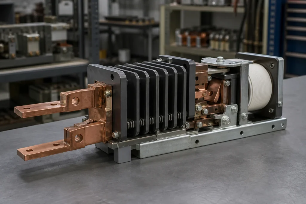
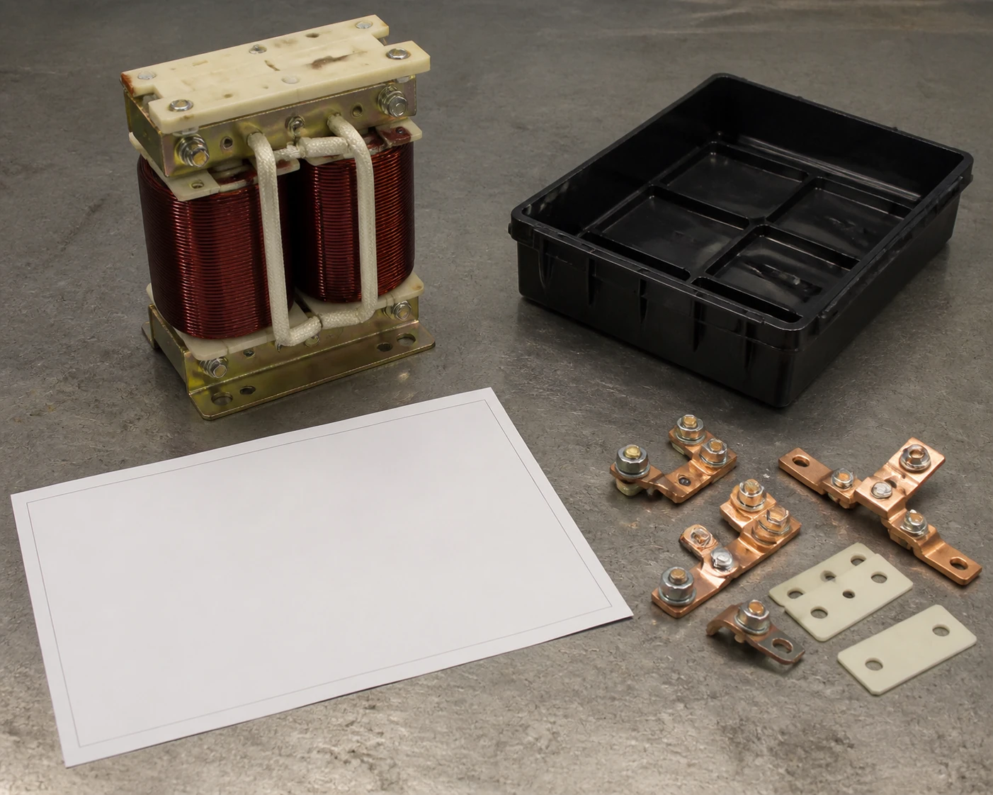
A magnetic blowout switch is a switching device that uses a dedicated magnetic coil to drive an electrical arc away from the contacts and into a quenching structure, extending contact life and enabling reliable interruption of DC or high-energy AC circuits. It is not a generic auxiliary contact, and an RFQ that treats it as one will produce wrong-fit quotations. Every RFQ for a magnetic blowout switch must capture the exact equipment model, the coil supply parameters, the contact configuration, and the arc-interruption context so that the quoted device actually matches the coordinated interrupter system it serves. The MV Switching Equipment category provides the wider installation context.
Functional Distinction: Magnetic Blowout Switch vs. Generic Auxiliary Contact
Auxiliary contacts and magnetic blowout switches occupy different roles even when they share a similar form factor or mounting location. Understanding the boundary prevents costly misidentification during procurement.
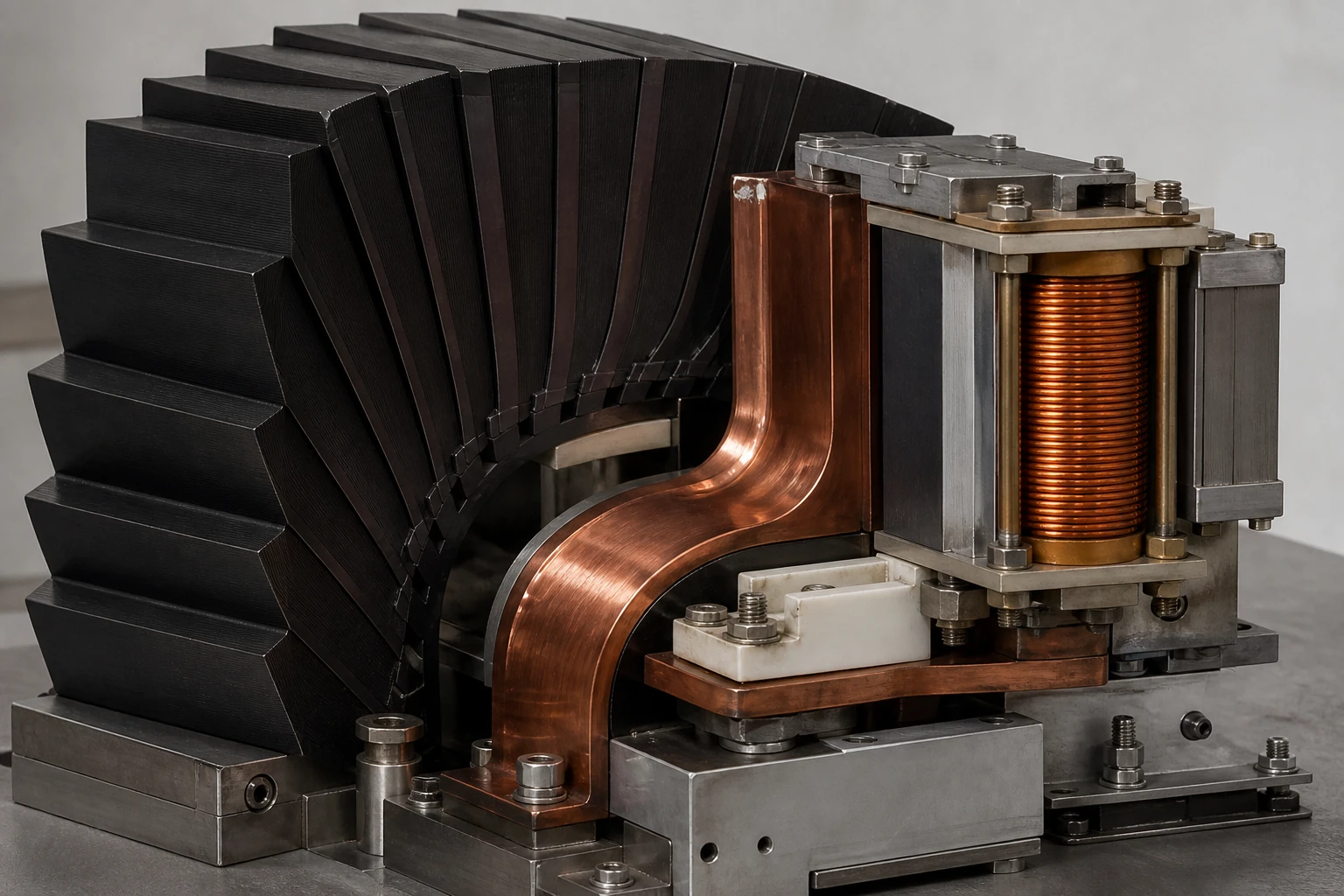
A standard auxiliary contact signals the position of a primary device—open, closed, tripped—to control or monitoring circuits. It carries only pilot-duty current and has no arc-management hardware. A magnetic blowout switch, by contrast, carries or interrupts enough current that the arc produced at contact separation must be actively managed. The blowout coil generates a magnetic field that forces the arc off the main contacts and onto dedicated arc runners, driving it into an arc chute where stacked fins cool and segment the arc column until it extinguishes.
The General Electric SE-9 Auto-blast Interrupter Switch instruction manual makes this coordination explicit: it identifies the blowout coil, arc runners, arcing tip, booster cylinder, and arc chute as a single coordinated interrupter system, describing the magnetic blowout action specifically as forcing the arc into the arc-chute fins. Removing or mismatching any one element changes the interruption characteristic of the whole assembly. A procurement substitution that ignores this coordination risks incomplete arc quenching, accelerated contact erosion, or outright failure to interrupt.
The practical takeaway is simple. If a device datasheet or nameplate references a blowout coil, arc runners, or an arc chute, the device is not an auxiliary contact and must not be sourced as one. The RFQ must reflect that distinction.
How the Magnetic Blowout Mechanism Works
The mechanism is electromagnetic, not mechanical. When the contacts begin to separate under load, an arc forms across the gap. Current flowing through the series-connected blowout coil produces a magnetic field perpendicular to the arc column. The Lorentz force created by the interaction of that field with the arc current pushes the arc laterally—off the main contact faces and along the arc runners toward the arc chute.
Inside the arc chute, metallic or ceramic fins divide the arc into multiple shorter segments. Each segment has its own cathode and anode voltage drop, so the total voltage required to sustain the arc rises rapidly. When that required voltage exceeds the circuit voltage, the arc extinguishes.
Several variables determine whether this sequence succeeds:
- **Coil ampere-turns.** The blowout coil must produce enough magnetic flux to move the arc at the expected current magnitude. An undersized coil at high current leaves the arc on the main contacts; an oversized coil at low current may blow the arc out so aggressively that it restrikes in an uncontrolled location.
- **Arc-runner geometry.** The runners provide a defined path from the contact gap to the chute entrance. Mismatched runners change the arc trajectory.
- **Arc-chute fin count and spacing.** These set the voltage-per-segment that the chute can impose on the arc. A chute designed for one voltage class may not extinguish arcs at a different voltage.
- **Polarity (DC circuits).** The Lorentz force direction depends on current direction. In DC applications, reversing polarity without reversing the blowout coil connection drives the arc away from the chute instead of into it. This is a failure mode that a generic part number cannot capture.
Because these variables are interdependent, the blowout switch is always part of a coordinated system. Sourcing it requires identifying the system, not just the switch.
Interface and Configuration Dependencies
A magnetic blowout switch does not exist in isolation. Its electrical and mechanical interfaces determine whether a replacement or new-install unit will function correctly.
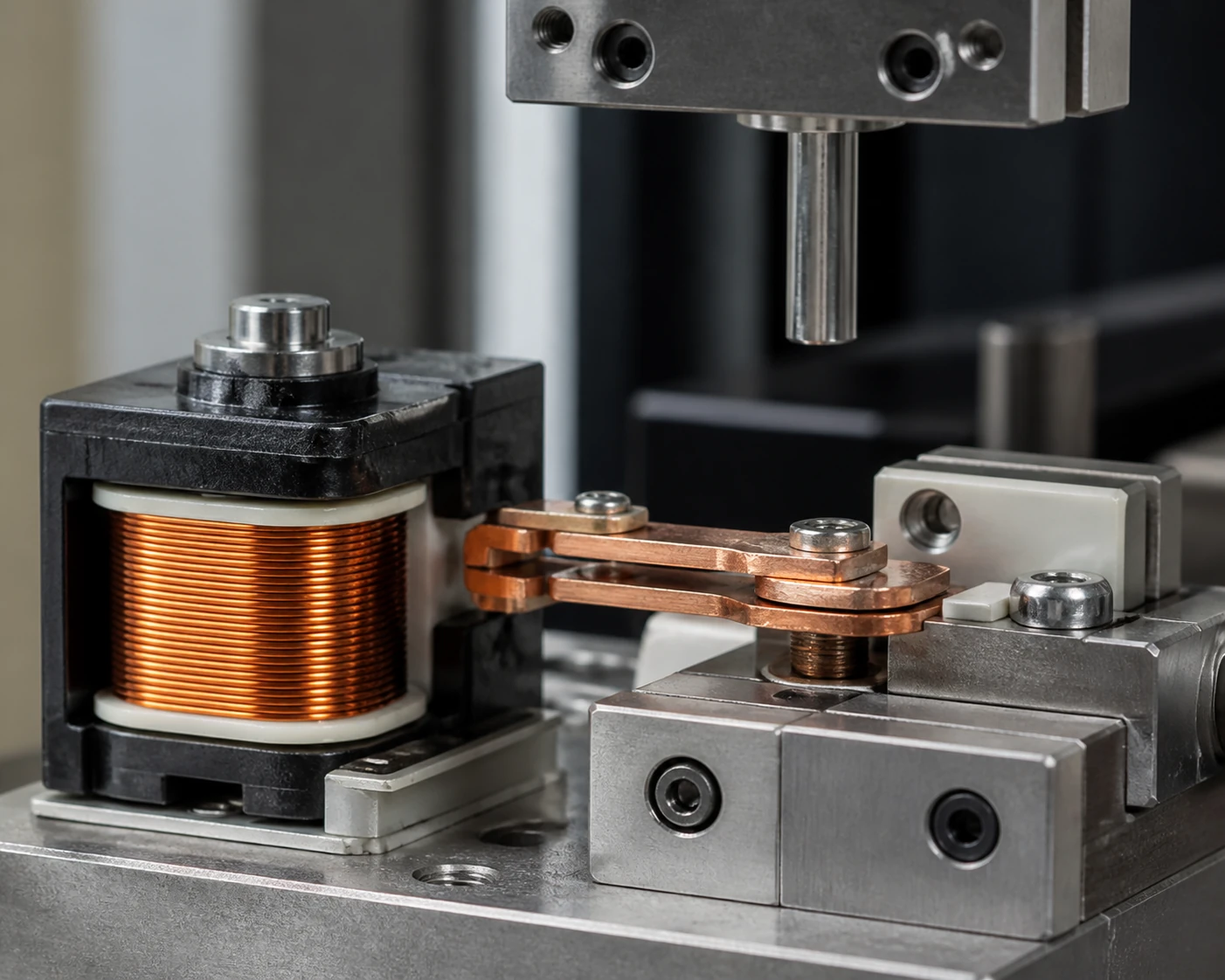
**Coil supply.** The blowout coil may be wired in series with the interrupted circuit (self-blown) or energized from a separate supply (independently blown). Series-blown coils scale their field with load current, which is an advantage for variable-load circuits but means the coil must tolerate the full fault current of the circuit. Independently blown coils require a defined supply voltage and current, and that supply must be reliable during the interruption event. The Schneider Electric 199ADBMYX-35 product record demonstrates this dependency: it explicitly combines contact configuration, coil supply parameters, and magnetic-blowout option into a single model-specific reference, confirming that the coil supply is not a secondary detail but a primary selection criterion.
**Contact configuration.** The number of poles, the normally-open or normally-closed state, the continuous current rating, and the voltage rating all interact with the blowout mechanism. A four-pole device with a blowout coil on only two poles, for instance, is not interchangeable with a two-pole device rated at higher current per pole, even if the total current capacity appears similar.
**Mounting and mechanical interface.** Blowout switches mount to specific breaker or contactor frames, draw-out chassis, or switchgear cells. Bolt patterns, operating-rod linkages, and arc-chute clearance dimensions are model-specific. A dimensionally similar device from a different product family may physically fit but misalign the arc path.
**Operating sequence and timing.** In circuit breakers with auto-blast or stored-energy mechanisms, the blowout switch opening may be sequenced with other interrupter actions—gas blast, puffer stroke, or spring release. The GE SE-9 manual's reference to a booster cylinder as part of the coordinated interrupter system illustrates this: the blowout coil's arc-driving action is timed against the booster cylinder's gas-blast action. A switch sourced without regard to that timing may interrupt too early, too late, or not at all.
What the RFQ Must Contain
An RFQ that says "magnetic blowout switch, 600 V, 200 A" will generate questions, delays, or wrong-fit quotations. The following data points eliminate ambiguity.
| RFQ Data Point | Why It Matters | Example |
|---|---|---|
| Equipment manufacturer and model | Defines the coordinated interrupter system | GE SE-9 Auto-blast Interrupter Switch |
| Exact switch part or catalog number | Prevents cross-referencing errors across product families | Schneider Electric 199ADBMYX-35 |
| Contact configuration (poles, NO/NC) | Determines electrical function and coil integration | 2NO + 2NC, series blowout on NO poles |
| Rated voltage (AC/DC) and voltage class | Affects arc-chute design and polarity requirements | 250 VDC |
| Rated continuous current | Sizes contacts and blowout coil | 200 A continuous |
| Coil supply type and parameters | Distinguishes series-blown from independent-blown | Series-blown, or 120 VAC independent |
| Mounting frame or cell designation | Ensures mechanical fit and arc-path clearance | Switchgear cell type, draw-out cradle model |
| Quantity and delivery requirement | Standard procurement data | 4 units, 12-week ARO |
If any of these fields cannot be filled from available documentation, the RFQ should flag the gap explicitly rather than leave it blank. A supplier who receives an incomplete RFQ will either guess or delay; neither outcome serves the buyer.
Verification Workflow Before Issuing the RFQ
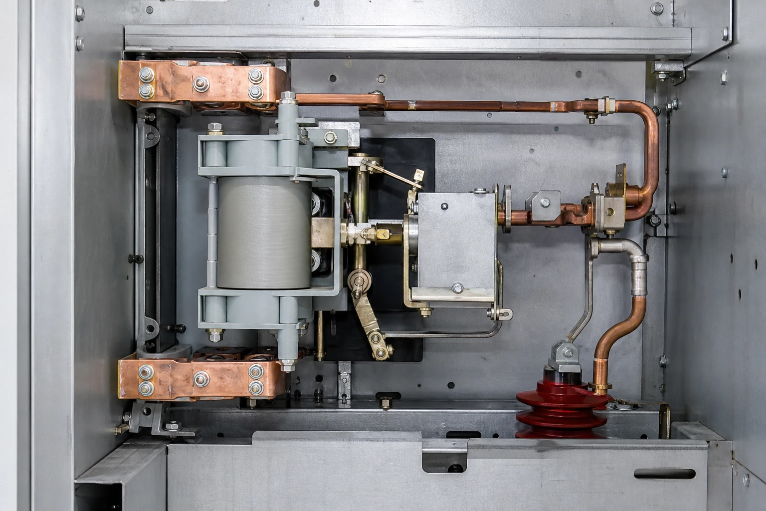
Before the RFQ leaves procurement, a short verification pass prevents the most common errors.
**Step 1: Confirm the device is a magnetic blowout switch.** Check the equipment nameplate, the original instruction manual, or the OEM parts list for references to a blowout coil, arc runners, or arc chute. If none of these terms appear, the device may be a standard auxiliary contact, and the RFQ scope changes accordingly.
**Step 2: Record the full OEM part number and revision.** Magnetic blowout switches evolve across equipment revisions. A part number without a revision suffix may map to multiple coil ratings or contact configurations. The Schneider Electric approach—encoding contact configuration, coil supply, and blowout option into a single model-specific reference—is the pattern to replicate in the RFQ, regardless of OEM.
**Step 3: Identify the coil circuit.** Trace the blowout coil wiring on the equipment schematic to determine whether it is series-blown or independently blown, and record the supply parameters. If the schematic is unavailable, state that in the RFQ; do not default to an assumption.
**Step 4: Confirm polarity requirements.** For DC applications, verify whether the switch is polarity-sensitive and document the expected current direction relative to the coil winding. Polarity reversal is a known failure mode that a generic specification will not prevent.
**Step 5: Check mechanical interface dimensions.** If the replacement is not an exact OEM part, confirm mounting bolt pattern, arc-chute clearance envelope, and operating-rod linkage compatibility from the equipment installation drawing.
**Step 6: Cross-check against the coordinated system.** Return to the equipment manual and confirm that no other interrupter component—booster cylinder, puffer mechanism, gas-blast valve—depends on the blowout switch's timing or position. If dependencies exist, note them so the supplier understands the integration context.
Model-specific approved procedures govern any physical inspection, adjustment, or testing actions required during this verification. The steps above address only the data-gathering boundary.
Standards and Evidence Boundaries
No single standard governs all magnetic blowout switches. The applicable standard depends on the host equipment:
- Medium-voltage circuit breakers fall under IEEE C37 series standards for switchgear.
- Low-voltage power circuit breakers and contactors reference UL 1066, UL 489, or IEC 60947 depending on jurisdiction and equipment class.
- Industrial control relays with magnetic blowout, like the Schneider Electric 199ADBMYX-35, may reference UL 508 or IEC 60947-5-1.
The RFQ should state the standard that governs the host equipment, not attempt to specify a standard for the blowout switch in isolation. The switch inherits its performance requirements from the system it serves.
Evidence from OEM documentation—such as the GE SE-9 manual—establishes the design intent and coordination requirements for a specific installation. It does not generalize to other manufacturers' equipment. Each RFQ must be grounded in the documentation for the actual installed equipment; related evidence-led material is available in the Technical Articles library.
Common Sourcing Errors and Their Consequences
Repeated procurement failures cluster around a few patterns.
**Substituting an auxiliary contact for a blowout switch.** The auxiliary contact lacks a blowout coil and arc chute. Under load, the arc dwells on the contacts, welds them shut, or erodes them to failure within a few operations. This is the most consequential error and the easiest to prevent: verify the presence of a blowout coil before scoping the RFQ.
**Matching current and voltage but ignoring coil type.** A switch rated for the correct current and voltage but with an independently blown coil cannot replace a series-blown unit without adding a separate coil supply circuit. The reverse substitution may expose the coil to fault currents it was not designed to carry.
**Ignoring DC polarity.** A blowout switch installed with reversed polarity in a DC circuit drives the arc away from the chute. The device may appear to function at low current but fail catastrophically under load. This error is invisible during commissioning unless a polarity-specific test is performed.
**Using a visually similar part from a different product family.** Mounting dimensions may align, but arc-runner geometry, chute fin spacing, or operating-rod engagement may differ. The switch installs cleanly and fails in service.
Each of these errors traces back to an RFQ that omitted one or more of the data points in the table above. Complete identification at the RFQ stage is the lowest-cost point of intervention. A verified evidence package can then support a model-specific request through the product range.
FAQ
What is a magnetic blowout switch?
A magnetic blowout switch is a switching device equipped with a dedicated blowout coil that generates a magnetic field to force the electrical arc away from the contacts and into an arc chute during contact separation. The arc chute segments and cools the arc until it extinguishes. This distinguishes the device from a standard auxiliary contact, which has no arc-management hardware and is designed only for pilot-duty signaling. The GE SE-9 manual identifies the blowout coil, arc runners, arcing tip, booster cylinder, and arc chute as elements of a coordinated interrupter system—removing or mismatching any element changes the interruption behavior of the assembly.
What is the difference between a magnetic blowout switch and a standard auxiliary contact?
A standard auxiliary contact signals device position to control or monitoring circuits and carries only pilot-duty current. It has no blowout coil, no arc runners, and no arc chute. A magnetic blowout switch carries or interrupts higher current levels and uses an electromagnetic mechanism to manage the arc produced at contact separation. Substituting one for the other will either leave a circuit without arc management or introduce unnecessary complexity and cost into a signaling application. The presence of a blowout coil on the nameplate, schematic, or parts list is the definitive identifier.
What information must an RFQ for a magnetic blowout switch include?
At minimum: the equipment manufacturer and model, the exact switch part or catalog number with revision, the contact configuration including number of poles and NO/NC assignment, rated voltage with AC or DC designation, rated continuous current, coil supply type and parameters distinguishing series-blown from independently blown, and the mounting frame or cell designation. The Schneider Electric 199ADBMYX-35 product record illustrates the principle: it combines contact configuration, coil supply, and magnetic-blowout option into one model-specific reference, demonstrating that these parameters are inseparable for correct identification.
What happens if a magnetic blowout switch is installed with reversed polarity?
In DC circuits, the Lorentz force that drives the arc into the chute depends on the direction of current flow through the blowout coil relative to the magnetic field orientation. Reversing polarity reverses the force direction, pushing the arc away from the arc chute instead of into it. The switch may appear functional at low currents but fail to interrupt under load, potentially causing sustained arcing, contact destruction, or equipment damage. This failure mode is not detectable from nameplate data alone and requires verification of the coil wiring against the circuit polarity during the pre-RFQ data-gathering step.
What standards apply to magnetic blowout switches?
No single standard covers all magnetic blowout switches. The applicable standard is determined by the host equipment: IEEE C37 series for medium-voltage switchgear, UL 1066 or UL 489 for low-voltage power circuit breakers, IEC 60947 for industrial switchgear and controlgear, and UL 508 or IEC 60947-5-1 for industrial control devices. The RFQ should reference the standard governing the host equipment rather than attempting to specify a standalone standard for the switch, because the switch inherits its performance and test requirements from the coordinated system it serves.

