

Quick Takeaway
- Confirm the project duty and applicable requirements for Instrument Transformers before selection or service work.
- Use recorded inspection and test evidence instead of unsupported assumptions.
- Keep the final acceptance, maintenance, and handover documents with the equipment record.
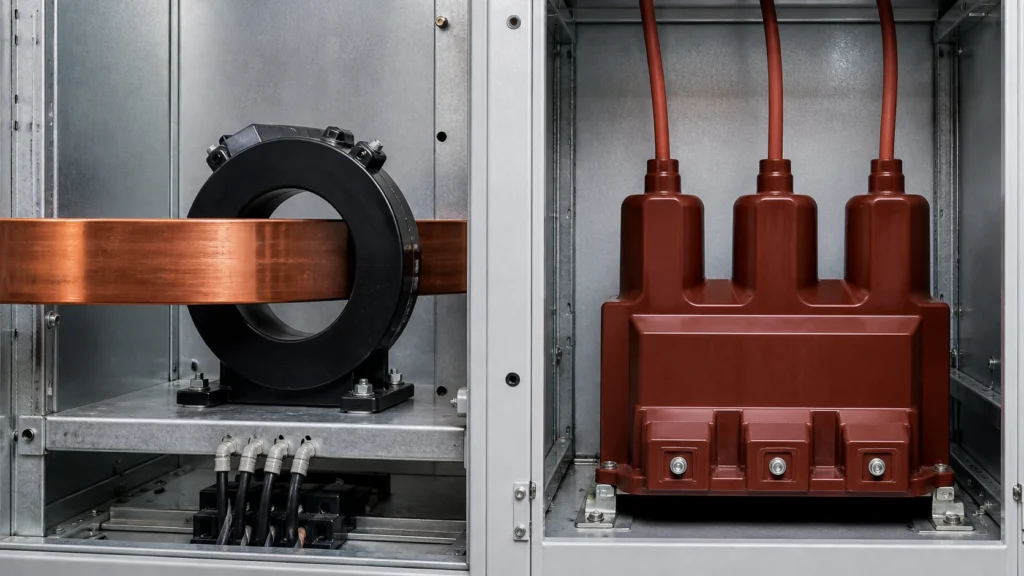
A current transformer (CT) senses line current by electromagnetic coupling with the primary conductor and delivers a proportional, reduced-current signal to metering or protection devices. A voltage transformer (VT) — whether electromagnetic or capacitive — senses system voltage and delivers a proportional, reduced-voltage signal to the same classes of device. Both belong to the instrument-transformer product family governed by IEC 61869-1:2023, but they monitor different electrical quantities, connect to the circuit differently, and carry different interface data into an RFQ. Specifying one where the other is needed, or mixing their interface requirements on a quote request, is among the most common procurement errors in medium-voltage and high-voltage projects.
| Attribute | Current Transformer (CT) | Voltage Transformer (VT) |
|---|---|---|
| Quantity sensed | Line current (A) | System voltage (V) |
| Primary connection | In series with the power conductor | In parallel (line-to-ground or line-to-line) |
| Secondary output (typical) | 1 A or 5 A | 110 V or 110/√3 V |
| Open-circuit hazard | Dangerous high voltage if secondary is opened under load | No equivalent hazard; secondary may be fused |
| Key RFQ electrical inputs | Rated primary current, short-time thermal current, dynamic current | Rated primary voltage, voltage factor, insulation level |
| Typical mounting concern | Conductor routing, busbar geometry, and CT window size | Bushing clearance, fuse accessibility, ferroresonance damping |
Functional Distinction: Why the Circuit Sees Two Different Devices
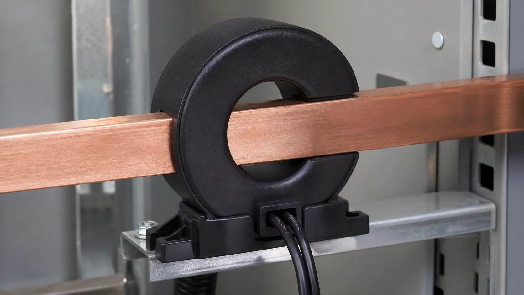
The fundamental difference is the point of insertion into the power circuit. A CT is a series device. Its primary winding — sometimes a single pass of the busbar through a toroidal core — carries the full load current, and the secondary winding reproduces that current at a safe, standardised magnitude. A VT is a shunt device. Its primary winding is connected across the voltage it must measure, and its secondary winding reproduces that voltage at a metering-safe level.
This series-versus-shunt distinction dictates almost every downstream engineering and procurement decision. A CT must withstand the full fault current of the system, including its thermal and dynamic peaks, without saturating in a way that blinds protective relays during the milliseconds when accurate measurement matters most. A VT must withstand the system's rated voltage continuously and its temporary overvoltage conditions, characterised by a voltage factor and duration defined in IEC 61869-1:2023, without ferroresonance or insulation degradation.
Because the two devices sit at different electrical nodes, their failure modes are also different. An open-circuited CT secondary, while the primary is energised, develops a hazardous voltage across its terminals and risks core damage. A VT secondary can be safely fused and disconnected. This single operational fact shapes wiring practice, terminal-block design, and the safety warnings that belong on every project drawing — and it is the reason CT and VT specifications must never be confused on a purchase order.
Electromagnetic and Mechanical Mechanism
Both CTs and VTs rely on transformer action: a time-varying flux in a magnetic core links two windings. The differences lie in how each device is optimised.
A metering-class CT is designed so that its secondary current tracks the primary current with minimal ratio and phase-angle error across a defined range, typically from a fraction of rated current up to rated current. A protection-class CT is designed to maintain acceptable accuracy up to high multiples of rated current so that relay elements see a faithful reproduction of fault current. The core material, cross-section, and air-gap characteristics are chosen accordingly. Window-type CTs, bar-primary CTs, and wound-primary CTs each impose a different mechanical interface on the switchgear or busbar arrangement — information that must appear on the RFQ.
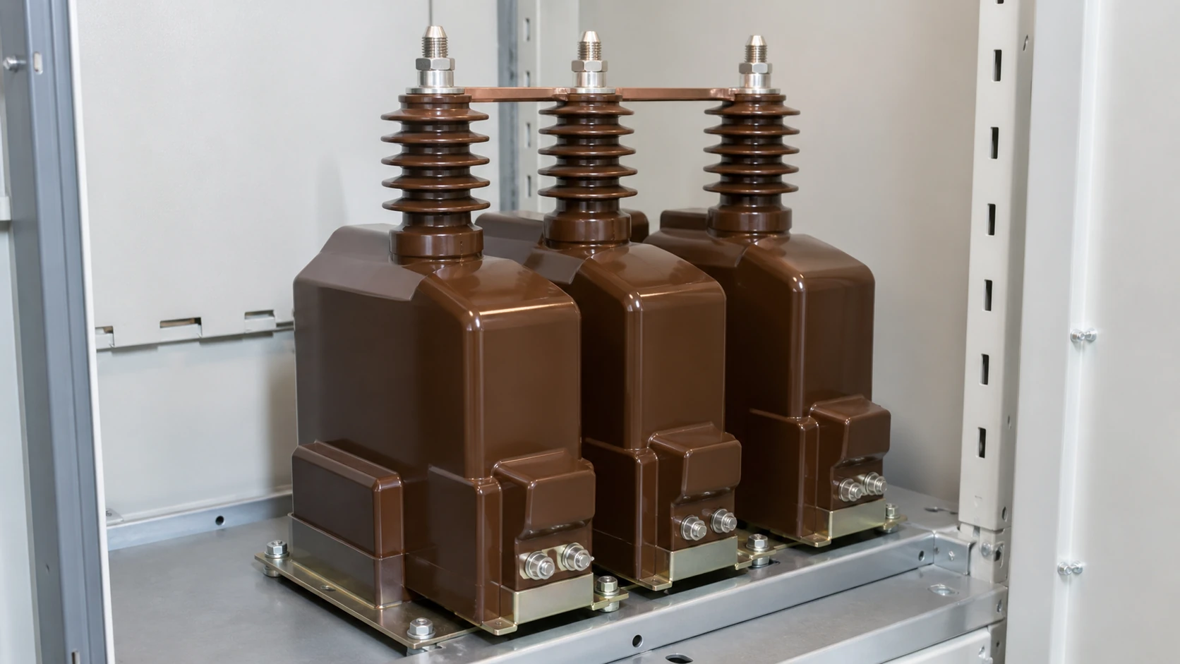
A VT, whether wound (electromagnetic) or capacitive, is optimised for voltage accuracy at or near rated voltage. Electromagnetic VTs use a conventional step-down transformer with high-permeability core steel. Capacitive voltage transformers (CVTs), used at transmission voltages, add a capacitive divider ahead of a smaller electromagnetic unit. The mechanical interface is dominated by insulation clearances, bushing lengths, and — for indoor medium-voltage VTs — the need for ferroresonance-damping circuits when connected to ungrounded or resonant-grounded systems.
Where CTs and VTs Appear Inside Switchgear
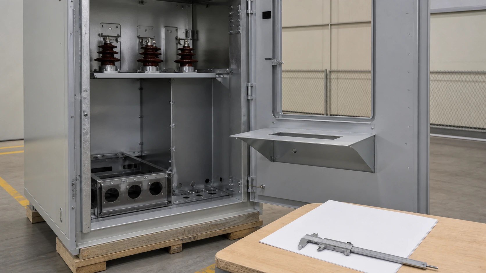
ABB's UniGear 500R catalogue illustrates a practical example: within a single medium-voltage switchgear panel, CTs and VTs serve distinct metering and protection roles and occupy different physical compartments. The CTs are installed on the cable or busbar connections where they can encircle the primary conductor in series. The VTs are installed in a dedicated compartment or on a voltage-sensing truck where they connect line-to-ground or line-to-line across the bus.
This physical separation matters for the RFQ because the mechanical interface — mounting dimensions, terminal orientation, and withdrawal clearance — is specific to the switchgear type and the compartment location. That interface belongs in the wider MV Switching Equipment context, not in a generic transformer-only data sheet. ABB's documentation makes clear that the selection inputs for a CT (primary current rating, short-time withstand, dynamic withstand, and the intended metering-or-protection duty) differ from the selection inputs for a VT (primary voltage rating, voltage factor, and the intended metering-or-protection duty). Submitting an RFQ that omits these role-specific inputs forces the manufacturer to assume values or to return a clarification request, adding lead time.
Standards and Evidence Boundaries
IEC 61869-1:2023 provides the general requirements for all instrument transformers — CTs and VTs alike — covering insulation, temperature rise, marking, and testing requirements for devices intended for use above 1 kV AC or 1.5 kV DC in measuring, protection, and control applications. Subsequent parts of the IEC 61869 series define the accuracy-class structure, output ratings, and type-test procedures specific to CTs and VTs respectively.
This article uses IEC 61869-1:2023 to frame the shared product-family boundary and to explain why both CTs and VTs appear on the same project specifications. It does not recommend specific ratios, burden values, accuracy classes, or protection settings. Those parameters must be determined through a project-specific engineering study that accounts for the network short-circuit level, relay burden, cable length, metering equipment input impedance, and the required accuracy at defined operating points. The RFQ should capture these parameters once they are determined; the sections below describe what data to assemble before issuing the request.
Selection Workflow: From Single-Line Diagram to RFQ Data
A practical selection sequence prevents the most frequent errors — ordering a CT where a VT is needed, specifying a metering-class device for a protection application, or omitting the mechanical interface data that determines physical fit.
**Step 1 — Identify every instrument-transformer location on the single-line diagram.** Each location is either a current-sensing point (CT) or a voltage-sensing point (VT). Mark the intended duty: metering, protection, or combined.
**Step 2 — Collect the system-level electrical data for each location.** For CTs: rated primary current, maximum continuous current, symmetrical short-circuit current, peak (dynamic) current, and the duration of fault withstand. For VTs: rated primary voltage, system grounding method, required voltage factor and its duration, and insulation level (BIL/SIL).
**Step 3 — Collect the secondary-side interface data.** This includes the connected burden (relay, meter, and cable impedance), the required output level (1 A or 5 A for CTs; 110 V or 110/√3 V for VTs), and the number of secondary windings or cores.
**Step 4 — Collect the mechanical interface data.** For switchgear-mounted devices, reference the switchgear manufacturer's instrument-transformer compartment drawings — as ABB does for UniGear 500R — to confirm mounting dimensions, terminal positions, and withdrawal clearances. For free-standing outdoor devices, reference the substation layout for phase spacing, foundation loads, and seismic requirements.
**Step 5 — Compile and review before issuing the RFQ.** The checklist in the next section organises these inputs into a single data package.
RFQ Data Checklist
The table below consolidates the minimum data fields an instrument-transformer manufacturer needs to return a technically compliant quotation. Omitting any field risks a quotation that does not fit the application or the switchgear.
| Data field | CT-specific | VT-specific | Common to both |
|---|---|---|---|
| Rated primary value | Rated primary current (A) | Rated primary voltage (kV) | — |
| Rated secondary value | 1 A or 5 A | 110 V or 110/√3 V | — |
| Intended duty | Metering, protection, or dual | Metering, protection, or dual | — |
| System fault data | Symmetrical short-circuit current, dynamic peak, duration | — | Rated insulation level (BIL/SIL) |
| Voltage factor | — | Voltage factor and duration | — |
| System grounding | — | Grounding method (affects VT voltage factor) | — |
| Secondary burden | Connected VA and power factor | Connected VA and power factor | — |
| Number of cores/windings | Per CT | Per VT | — |
| Mounting type and dimensions | Window size, bar dimensions, or switchgear model | Switchgear model, bushing clearances | Indoor/outdoor, altitude, ambient temperature |
| Applicable standard and edition | — | — | IEC 61869 series (specify parts) or regional equivalent |
| Project and tag information | — | — | Tag number, project name, quantity, delivery schedule |
Accuracy class and rated output (burden) are project-specific engineering outputs, not values this article prescribes. Include them on the RFQ once they have been determined by the responsible engineer.
Installation, Interface, and Failure Risks
Several risks recur in instrument-transformer projects and can be mitigated before the RFQ is issued or during incoming inspection.
**Wrong device type ordered.** This happens when the single-line diagram annotation is ambiguous. A clear CT-versus-VT callout at every instrument-transformer location, confirmed during the selection workflow above, eliminates the error.
**Mechanical misfit.** A CT whose window is too small for the busbar, or a VT whose bushing height exceeds the switchgear compartment, cannot be installed. Including the switchgear manufacturer's compartment drawing in the RFQ — as ABB's UniGear documentation enables — gives the instrument-transformer manufacturer the data to confirm fit.
**Secondary-circuit errors.** Connecting a CT secondary to a high-impedance circuit (effectively open-circuiting it) creates a safety hazard. Connecting a VT secondary to a low-impedance load effectively short-circuits it. Both errors trace to wiring that does not respect the series-versus-shunt nature of the device. The RFQ should specify the secondary terminal arrangement and any shorting-terminal-block requirements for CTs.
**Ferroresonance in VT circuits.** Electromagnetic VTs connected to ungrounded or resonant-grounded systems can sustain ferroresonance, causing overvoltage and VT damage. The system grounding method must be stated on the RFQ so the manufacturer can advise on damping requirements.
Model-specific approved procedures govern all live installation, commissioning, and maintenance actions. This article addresses the evidence, verification, and data-assembly boundary that precedes those procedures.
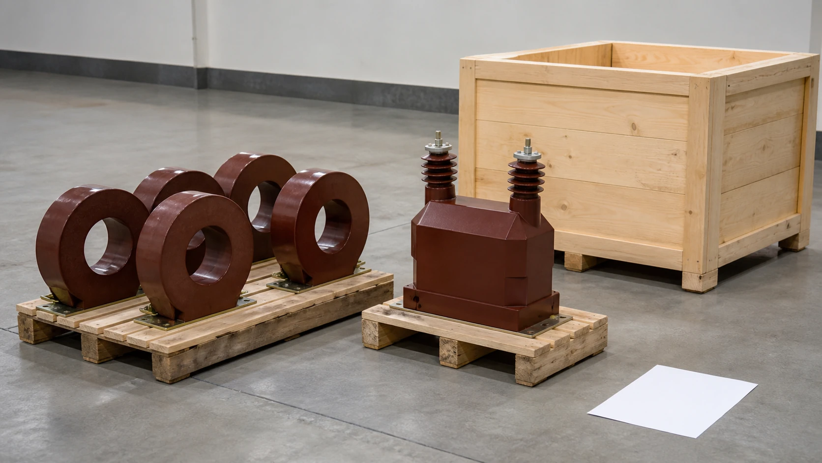
Bringing CTs and VTs Together on One RFQ
Many projects require both CTs and VTs for the same switchgear lineup. Combining them on a single RFQ to one manufacturer can simplify commercial handling, but the technical data must still be separated by device type because the input fields differ. A well-structured RFQ groups each instrument-transformer tag with its role (CT or VT), its electrical data, its mechanical interface data, and its intended duty. The comparison table at the opening of this article and the checklist above provide the framework for that grouping; the Technical Articles library can support related evidence checks before a request is sent.
When the RFQ is directed to a switchgear OEM — as in the ABB UniGear 500R context — the instrument transformers may be quoted as part of the switchgear package. Even then, the project engineer should verify that the CT and VT specifications match the system study outputs, rather than accepting default selections without review.
Reeuini's product range covers both CTs and VTs for medium-voltage applications. Submitting the data outlined in this article ensures the quotation process starts from a technically complete baseline, reducing revision cycles and lead-time risk.
FAQ
What is the primary difference between a current transformer and a voltage transformer?
A current transformer is connected in series with the power conductor and senses line current, delivering a proportional reduced-current output (typically 1 A or 5 A). A voltage transformer is connected in parallel across the voltage source and senses system voltage, delivering a proportional reduced-voltage output (typically 110 V or 110/√3 V). They monitor different electrical quantities, connect to the circuit at different points, and carry different specification data into an RFQ.
What is the risk of open-circuiting a current transformer secondary?
When a CT secondary is open-circuited while the primary carries current, the full magnetising flux drives a dangerously high voltage across the secondary terminals. This can damage the CT's insulation, pose an electric-shock hazard to personnel, and degrade the magnetic core. For this reason, CT secondaries must be short-circuited before any connected device is disconnected. This hazard does not apply to VTs, whose secondaries can be fused and safely isolated.
What is IEC 61869-1:2023 and how does it relate to CTs and VTs?
IEC 61869-1:2023 is the general-requirements standard for instrument transformers, covering insulation coordination, temperature rise, marking, and testing for devices rated above 1 kV AC or 1.5 kV DC used in measuring, protection, and control. It establishes the shared product-family framework under which both CTs and VTs are specified and tested. Subsequent parts of the IEC 61869 series provide the accuracy, burden, and type-test details specific to each device type.
What is the minimum data needed to request a quotation for instrument transformers?
At minimum, each instrument-transformer line item on an RFQ needs: the device type (CT or VT), rated primary and secondary values, intended duty (metering, protection, or both), system fault or voltage-factor data as applicable, connected burden, number of secondary windings, mounting type and mechanical interface dimensions, applicable standard, and project tag information. The RFQ data checklist in this article provides the full field-by-field breakdown for both CTs and VTs.
What is ferroresonance and why does it matter for voltage transformers?
Ferroresonance is a nonlinear oscillation that can occur when an electromagnetic VT's magnetising inductance interacts with system capacitance, typically on ungrounded or resonant-grounded networks. It can cause sustained overvoltages that damage the VT and connected equipment. Stating the system grounding method on the RFQ allows the manufacturer to specify appropriate ferroresonance-damping measures. This phenomenon does not affect CTs because their series connection and low-impedance secondary circuit do not create the resonant conditions.

