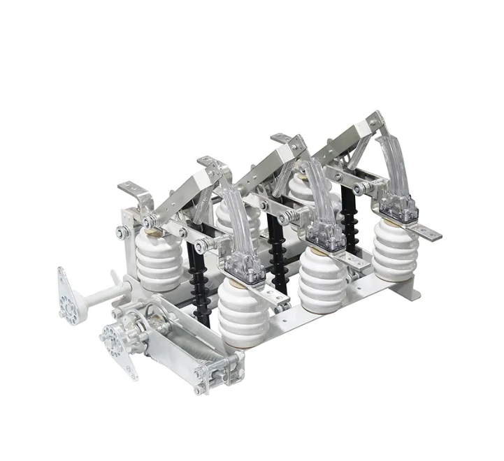
Compare indoor and outdoor medium voltage disconnect switches for switchgear, substations and line-isolation applications from 10 kV to 252 kV. Review 13 model records by current, withstand rating, operating mechanism, environment and available drawings.
Medium Voltage Disconnect Switch Models: Indoor, Outdoor and Fuse-Switch
Compare six indoor disconnect switches, six outdoor disconnect switches and one separate RGW1 fuse-switch combination. Filter by installation, then open any model for complete ratings, operating data, site conditions and available dimensional drawings.
13 product records shown
Disconnect Switch Model Technical Specifications
Application and Model Notes
Complete Ratings and Technical Data
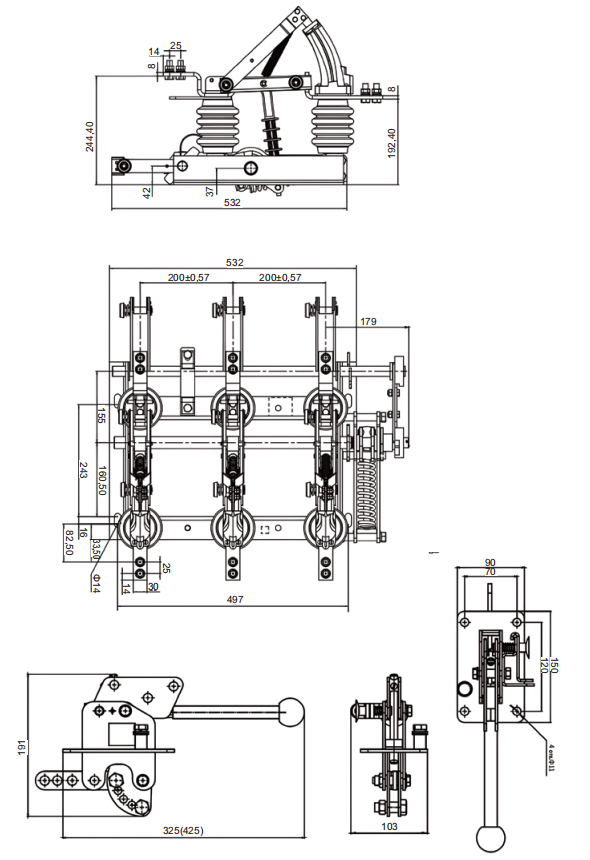
Outline and Installation Drawings
Open an available drawing at full size to compare mounting dimensions, terminals, phase spacing and operating interfaces.
Information to Include in Your RFQ
Send the required function, model if known, voltage and current, short-circuit duty, indoor or outdoor installation, mechanism, earthing-blade requirement, site conditions, quantity and destination. Include the installed nameplate and interface drawing for replacement projects.
Full-size engineering drawing
Complete technical parameters
Complete technical parameters
Item
Unit
Published value
Rated voltage Unom / maximum operating voltage Upr
kV
10 / 12
Rated current
A
400, 630
Rated breaking current at power factor cosφ > 0.7
A
400, 630
Maximum breaking current at power factor cosφ > 0.7
A
800
Maximum short-circuit current, dynamic stability
kA
51
Short-circuit current power-frequency component, Ihn
kA
20
Short-circuit duration, tk3
s
1
Maximum rated closing current
kA
51
1 s RMS current, thermal stability
kA
20
Maximum main-circuit DC resistance in closed position
mΩ
100
Minimum rated on-off operations under normal conditions
operations
10
Working environment
Working environment
No.
Condition
1
Altitude not exceeding 1,000 m
2
Ambient air temperature from -25 °C to +40 °C
3
Relative humidity: daily average not exceeding 95%; monthly average not exceeding 90%
4
Seismic intensity not exceeding 8 degrees
5
Installation site free from fire, flammable or explosive hazards, severe pollution, chemical corrosion and strong vibration
Complete technical parameters
Complete technical parameters
Parameter
Condition
Unit
General
400 A
630 A
1000 / 1250 A
Rated voltage
kV
12
1 min power-frequency withstand voltage
To earth
kV
42
1 min power-frequency withstand voltage
Across open contacts
kV
48
Lightning impulse withstand voltage, peak
To earth
kV
75
Lightning impulse withstand voltage, peak
Across open contacts
kV
85
Rated frequency
Hz
50
Rated current
A
400
630
1000 / 1250
Rated short-time withstand current
kA
16 / 20
16 / 20 / 25
20 / 25 / 31.5
Rated peak withstand current
kA
40 / 50
40 / 50 / 63
50 / 63 / 80
Rated short-time withstand duration
Main blade / earthing blade
s
4 / 2
Creepage distance
mm
300-380
Mechanical life
operations
2000
Complete technical parameters
Complete technical parameters
Parameter
Test or condition
Unit
Data 1
Data 2
Rated voltage
kV
12
Rated frequency
Hz
50
Rated current
A
1600-2000
2500-3150
Rated short-time withstand current
kA
40
50
Rated peak withstand current
kA
100
125
Rated short-time withstand-current duration
s
4
Rated insulation level
1 min power-frequency withstand voltage
kV
Pole-to-pole and pole-to-earth 42; across open contacts 48
Rated insulation level
Lightning impulse withstand voltage, peak
kV
Pole-to-pole and pole-to-earth 75; across open contacts 85
Complete technical model data
Complete technical model data
Model
Rated voltage
Rated current
Short-time withstand current / duration
Peak withstand current
Lightning impulse to earth / across distance
1 min power-frequency to earth / across distance
GN27-40.5/630-20
40.5 kV
630 A
20 kA / 4 s
50 kA
185 / 215 kV
95 / 115 kV
GN27-40.5/1250-31.5
40.5 kV
1250 A
31.5 kA / 4 s
80 kA
185 / 215 kV
95 / 115 kV
Working environment
Working environment
No.
Condition
1
Altitude not more than 1,000 m
2
Ambient air temperature: upper limit +40 °C; lower limit -10 °C
3
Relative humidity: daily average below 95%; monthly average below 90%
4
Earthquake intensity not more than 8 degrees
5
Installation site free from serious dust and corrosive or explosive substances
6
Installation site free from frequent violent vibration
Complete technical model matrix
Complete technical model matrix
Parameter
400 A
630 A
1000 A
1250 A
Main model
GN30-12/400-12.5
GN30-12/630-20
GN30-12/1000-31.5
GN30-12/1250-31.5
Earthing-switch model
GN30-12D/400-12.5
GN30-12D/630-20
GN30-12D/1000-31.5
GN30-12D/1250-31.5
Rated voltage
10 kV
10 kV
10 kV
10 kV
Highest voltage
12 kV
12 kV
12 kV
12 kV
Rated current
400 A
630 A
1000 A
1250 A
Thermal stability current
12.5 kA
20 kA
31.5 kA
31.5 kA
Thermal stability time
4 s
4 s
4 s
4 s
Dynamic current
31.5 kA
50 kA
80 kA
80 kA
Rated impulse withstand voltage
Earth / phase 75 kV; open distance 85 kV
Earth / phase 75 kV; open distance 85 kV
Earth / phase 75 kV; open distance 85 kV
Earth / phase 75 kV; open distance 85 kV
1 min power-frequency withstand voltage
Earth / phase 42 kV; open distance 48 kV
Earth / phase 42 kV; open distance 48 kV
Earth / phase 42 kV; open distance 48 kV
Earth / phase 42 kV; open distance 48 kV
Complete technical parameters
Complete technical parameters
Item
Unit
Published value
Nominal voltage
kV
10
Number of poles
3
Rated current
A
630
Protection grade
IP00
Maximum operating voltage
kV
12
Rated thermal stability current
kA
10
Rated frequency
Hz
50 / 60
Weight
kg
26
Narrative insulation resistance reference
MΩ
≥ 1000
Narrative mechanical endurance reference
operations
≥ 2000
Narrative power reference at 630 A
W
21.8
Ambient conditions
Ambient conditions
No.
Condition
1
Altitude ≤ 3,000 m
2
Ambient temperature from -30 °C to +50 °C
3
Wind speed ≤ 35 m/s
4
Air-pollution class IV
5
Earthquake intensity ≤ 8 degrees
6
Ice thickness ≤ 10 mm
Complete technical specifications
Complete technical specifications
Item
Condition
Unit
General
12 kV
24 kV
40.5 kV
Rated voltage
kV
12 / 24 / 40.5
Rated current
A
630 / 1000 / 1250
Rated power frequency
Hz
50 / 60
Rated peak withstand current
kA
50 / 63
Rated short-time withstand current
kA
20 / 25
Rated short-time withstand duration
s
4
Main-loop resistance
µΩ
≤ 80
≤ 90
≤ 100
1 min dry power-frequency withstand voltage
Phase-to-phase / phase-to-earth / open contacts
kV
42 / 48
50 / 60
95 / 115
1 min wet power-frequency withstand voltage
Phase-to-phase / phase-to-earth / open contacts
kV
34
50
85
Lightning impulse withstand voltage, peak
Phase-to-phase / phase-to-earth / open contacts
kV
75 / 85
125 / 145
185 / 215
Mechanical life
operations
2000
Structure features
Structure features
Component
Published description
General structure
Frame, operating insulator, stationary contact, blade, linkage spring mechanism and related components
Frame
5 mm-thick bent steel plate with mounting holes for the post insulators
Post and operating insulators
ZS-12 and 40.5-series outdoor post insulators; minimum bending resistance load 4,000 N
Stationary contact
Copper plate fixed to the post insulator
Blade
Rectangular copper plate with compression spring for pressure adjustment
Installation
Vertical or horizontal outdoor installation; operation with a CS□ mechanism
Ambient conditions
Ambient conditions
No.
Condition
1
Altitude ≤ 1,000 m
2
Ambient temperature from -25 °C to +40 °C
3
Installation site free from flammable or explosive materials and severe vibration
Permitted no-load switching conditions
Permitted no-load switching conditions
No.
Condition
1
Opening and closing a voltage transformer used for metering
2
Opening and closing busbar charging current
3
Opening and closing a power transformer’s no-load current when transformer capacity is below 750 kVA
Scope
These operations apply when a circuit breaker is not installed or is unavailable due to a fault
Complete technical specifications
Complete technical specifications
Item
Unit
400 / 630 A
800 / 1000 A
1250 A
Note
Rated voltage
kV
12
12
12
Rated current
A
400 / 630
800 / 1000
1250
Rated peak withstand current
kA
50
63
100
Earthing-switch data is stated as the same as the main switch
Rated short-time withstand current, 4 s
kA
20
25
40
Ambient conditions
Ambient conditions
No.
Condition
1
Altitude ≤ 3,000 m
2
Ambient temperature from -25 °C to +40 °C
3
Wind speed ≤ 35 m/s
4
Pollution degree ≤ Class III
5
Earthquake intensity ≤ 8 degrees
6
Installation site free from flammable or explosive substances and corrosive gas
7
Applicable standards: IEC 62271-103, GB 1985 and related standards
10 to 20 kV technical data
10 to 20 kV technical data
Item
Condition
Unit
10 kV
15 kV
20 kV
Rated voltage
kV
10
15
20
Maximum voltage
kV
12
17.5
24
Rated current
A
400 / 630 / 1250
400 / 630 / 1250
400 / 630 / 1250
Rated thermal stability current, 4 s RMS
kA
16
20
31.5
Rated dynamic stability current, peak
kA
40
50
80
1 min power-frequency withstand voltage
To earth
kV
42
42
45
1 min power-frequency withstand voltage
Across open contacts
kV
50
50
55
Rated lightning impulse withstand voltage, peak
To earth
kV
75
75
105
Rated lightning impulse withstand voltage, peak
Across open contacts
kV
85
85
125
Terminal rated static tension
N
500
500
500
40.5 kV model data
40.5 kV model data
Model
Rated voltage
Rated current
Peak withstand current
4 s short-time withstand current
GW4-40.5 / GW4-40.5D
40.5 kV
400 A
50 kA
20 kA
GW4-40.5 / GW4-40.5D
40.5 kV
630 A
50 kA
20 kA
GW4-40.5 / GW4-40.5D
40.5 kV
1000 A
63 kA
25 kA
GW4-40.5 / GW4-40.5D
40.5 kV
1250 A
80 kA
31.5 kA
Ambient conditions
Ambient conditions
No.
Condition
1
Altitude ≤ 3,000 m
2
Ambient temperature from -25 °C to +40 °C
3
Wind speed ≤ 35 m/s
4
Earthquake intensity ≤ 8 degrees
5
Ice thickness ≤ 10 mm
6
Anti-pollution version intended for heavily polluted areas
7
Installation site free from flammable or explosive materials and severe vibration
Electrical and mechanical ratings
Electrical and mechanical ratings
Item
Condition
Unit
72.5 kV
126 kV
145 kV
Rated voltage
kV
72.5
126
145
Rated current
Available ratings
A
630 / 1250 / 1600 / 2000
630 / 1250 / 1600 / 2000
630 / 1250 / 1600 / 2000
Rated peak withstand current
kA
63
80
100
4 s short-time withstand current
kA
25
31.5
40
Rated short-time withstand time
s
3 / 4
3 / 4
3 / 4
Rated power frequency
Hz
50 / 60
50 / 60
50 / 60
1 min power-frequency withstand voltage
Phase to earth
kV
160
230
275
1 min power-frequency withstand voltage
Across open contacts
kV
200
230 + 70
315
Lightning impulse withstand voltage, peak
Phase to earth
kV
350
550
650
Lightning impulse withstand voltage, peak
Across open contacts
kV
410
550 + 100
750
Main-blade open-contact force
N
≥ 900
≥ 1200
≥ 1500
Single-phase weight
kg
250
300
350
Mechanical endurance
operations
2000
2000
2000
Operating mechanism
Main blade
CJ6B or CS17
CJ6B or CS17
CJ6B or CS17
Operating mechanism
Earthing blade
CS17
CS17
CS17
Applicable standard
IEC 62271-102
IEC 62271-102
IEC 62271-102
Main-loop resistance
Main-loop resistance
Rated current
Unit
72.5 kV
126 kV
145 kV
630 A
µΩ
≤ 200
≤ 225
≤ 250
1250 A
µΩ
≤ 125
≤ 150
≤ 175
1600 A
µΩ
≤ 80
≤ 120
≤ 125
2000 A
µΩ
≤ 80
≤ 120
≤ 125
Operating mechanism parameters
Operating mechanism parameters
Item
Unit
CJ6B motor
CS17 manual
Additional value
Main-shaft output angle
°
90
90
Rated output torque
N·m
500
Motor power
W
370
Motor voltage
V
AC 380 / DC 220
Motor rated / starting current
A
1.3 / 4
Motor speed
r/min
1440
Control voltage
V
AC 220 / DC 220
Protection grade
IP54
IP54
Mechanical life
operations
10000
10000
Auxiliary-switch contacts
pairs
10NO + 10NC
4NO + 4NC or 8NO + 8NC
Opening / closing time
s
5 ± 1
Mechanism weight
kg
90
Manual mechanism weight
kg
15 without earthing
20 single earthing; 30 double earthing
Structure and product features
Structure and product features
No.
Published description
1
Self-lubricating composite shaft sleeve; stainless-steel or aluminum-bronze pins and shafts
1.2
Sealed upper and lower shaft-base frame with molybdenum lubricating grease
1.3
Reliable open and close position limiting
1.4
Adjustable clamp between the mechanism output shaft and switch drive shaft
2
Corrosion treatment selected by component, including hot-dip galvanizing, hot-extruded zinc coating or painting
2.2
Standard parts are stainless steel or hot-dip galvanized; fasteners below M10 are stainless steel
Main electrical circuit uses fixed connections to improve stability
3.3
Optional self-force contact uses contact-finger flexibility and electrodynamic force
Mechanism 1
CS17 manual mechanism includes frame, auxiliary switch and handle; approximate weight 15 kg
Mechanism 2
CJ6B motor mechanism uses a stainless-steel enclosure and integrated secondary controls
Mechanism 3
Motor or manual operating mechanism can be selected
Mechanism 4
Mechanism box can be fitted with a DSW4 electromagnetic lock
Ambient conditions
Ambient conditions
No.
Condition
1
Altitude ≤ 1,000 m
2
Ambient temperature from -40 °C to +40 °C
3
Wind speed ≤ 34 m/s
4
Pollution degree ≤ Class III
5
Earthquake intensity ≤ 8 degrees
6
Ice thickness ≤ 10 mm
Basic specifications
Basic specifications
Item
Unit
Published family values
Rated voltage
kV
40.5 / 72.5 / 126 / 145
Rated current
A
630 / 1250 / 1600 / 2000
Rated peak withstand current
kA
63 / 80 / 100
4 s short-time withstand current
kA
25 / 31.5 / 40
Rated short-time withstand time
s
3 / 4
Rated power frequency
Hz
50 / 60
Detailed insulation and voltage data
Detailed insulation and voltage data
Item
Condition
Unit
40.5 kV
126 kV
252 kV
Rated voltage
kV
40.5
126
252
1 min power-frequency withstand voltage
To earth
kV
95
230
460
1 min power-frequency withstand voltage
Across interrupter
kV
115
245
460 + 145
Lightning impulse withstand voltage, peak
To earth
kV
185
550
1050
Lightning impulse withstand voltage, peak
Across interrupter
kV
215
630
1050 + 200
Rated frequency
Hz
50
50
50
Rated-current parameters
Rated-current parameters
Rated current
Short-time withstand current
Peak withstand current
Short-circuit duration
630 A
20 kA
50 kA
4 / 2 s
1250 A
31.5 kA
80 kA
4 / 2 s
1600 A
40 kA
100 kA
4 / 2 s
2000 A
40 kA
100 kA
4 / 2 s
Mechanical load, creepage and life
Mechanical load, creepage and life
Item
Condition
Unit
40.5 kV
126 kV
252 kV
Rated mechanical terminal load
Horizontal and vertical load
N
750
1000
1000
Rated mechanical terminal load
Horizontal load
N
500
750
750
Rated mechanical terminal load
Vertical force
N
750
1000
1000
Creepage distance
mm
1013-1256
1813-2248
3150-3906
Mechanical life
operations
2000
2000
2000
Operating mechanism parameters
Operating mechanism parameters
Actuator
Item
Published value
Manual
Model
CD17 / CS17G
Manual
Control-loop voltage
AC 220 / DC 110 / DC 220 V
Motor
Model
CJ6
Motor
Motor voltage
AC 220 / AC 380 / DC 220 V
Motor
Control-loop voltage
AC 220 / AC 380 / DC 220 V
Motor
Closing time
6 ± 1 s
General
Mechanical life
2000 operations
Structure and installation
Structure and installation
Section
Published description
General construction
Three single-phase units; each phase has a V-type arrangement with a symmetrical angle of 50 degrees
Earthing-switch version
Adds male and female contacts, a blade, drive components and an interlock plate
Operating mechanisms
Main blade: CJ6 motor or CS17 manual; earthing blade: CS17 manual
Installation
Front, side, diagonal or reverse arrangement; indoor or outdoor use according to project requirements
Order information
Order information
No.
Information required
1
Type and specification of the outdoor disconnector
2
Working environment: ambient temperature, altitude and pollution level
3
Type of operating mechanism
4
Name and quantity of accessories and tools, ordered separately
Complete technical data
Complete technical data
Item
Condition
Unit
General
40.5 kV
72.5 kV
126 kV
Rated voltage
kV
40.5
72.5
126
1 min power-frequency withstand voltage
To earth / across interrupter
kV
95
160
230
Lightning impulse withstand voltage, peak
To earth / across interrupter
kV
185
350
550
Rated frequency
Hz
50
Rated current
A
630
Rated short-time withstand current
kA
8
Rated peak withstand current
kA
20
Rated short-circuit duration
Knife / sword
s
3
Rated mechanical terminal load
Horizontal and vertical load
N
750
Rated mechanical terminal load
Horizontal load
N
500
Rated mechanical terminal load
Vertical force
N
750
Creepage distance
Published values
mm
1013, 1256, 1813, 2284, 3150
Mechanical life
operations
10000
Production weight
Without earthing switch
kg
80
120
190
Operating mechanism parameters
Operating mechanism parameters
Actuator
Item
Unit
Published value
Motor
Model
CJ6B
Motor
Motor voltage
V
AC 380 / AC 220 / DC 220 / DC 110
Motor
Control-loop voltage
V
AC 380 / AC 220 / DC 220 / DC 110
Motor
Closing time
s
6 ± 1
Manual
Model
CS8-5
Manual
Electromagnetic-lock voltage
V
DC 220 / AC 220
Complete technical data
Complete technical data
No.
Item
Unit
12 kV column
36
1
Rated voltage
kV
12
36
2
Rated current
A
100
100
3
Rated frequency
Hz
50 / 60
50 / 60
4
Rated short-time withstand current
kA
25
31.5
5
Rated short-circuit duration
s
3
3
6
Rated active-load breaking current
A
200 / 400 / 630
200 / 400 / 630
7
Rated loop breaking current
A
200 / 400 / 630
200 / 400 / 630
8
Rated cable-charging current
A
12
12
9
5% rated active-load breaking current
A
31.5
31.5
10
Rated short-circuit making current
kA
63
63
11
Main-loop resistance
µΩ
≤ 100
≤ 100
12
Power-frequency withstand voltage to earth and between phases
kV RMS
50
50
13
Power-frequency withstand voltage across isolating distance
kV RMS
60
70
14
Lightning impulse withstand voltage to earth and between phases, peak
kV
125
170
15
Lightning impulse withstand voltage across air gap, peak
kV
145
195
16
Mechanical life
operations
10000
10000
17
Three-phase closing asynchronism
ms
≤ 5
≤ 5
Disconnect switch selection guide
How to Select a Medium Voltage Disconnect Switch
Start with the required switching function, then match the electrical ratings, installation environment, operating mechanism and physical interface. These five inputs help engineers select a model and give purchasing a complete basis for quotation.
01 Function and installation
Isolation-only duty or specified load switching, indoor switchgear or outdoor substation mounting, new supply or replacement application.
02 System ratings
Rated voltage, frequency, continuous current, short-time and peak withstand current, required duration and insulation level.
03 Site conditions
Altitude, ambient temperature, wind, pollution, ice and seismic requirements where applicable to the selected indoor or outdoor model.
04 Mechanism and interlocking
Manual or motor operation, control voltage, operating side, main and earthing blade arrangement, auxiliary contacts and interlocking requirements.
05 Interface and RFQ details
Phase spacing, mounting and terminal dimensions, shaft position, approved drawing, quantity, delivery country and required documents.
Product range by installation
Indoor, Outdoor and Fuse-Switch Configurations
Choose the product group by installation and switching function, then compare the exact model ratings, mechanism and dimensional interface. The range includes six indoor disconnect switches, six outdoor disconnect switches and one separate RGW1 fuse-switch combination.
01Switchgear installation
Indoor medium voltage disconnect switches
Typical applications
Isolation positions inside air-insulated or metal-enclosed switchgear
10 kV, 12 kV and 40.5 kV equipment configurations
New panels, retrofit projects and model-specific replacements
Compare these details
BHA, GN19, GN22, GN27, GN30 and RVZ model ratings
Mounting, terminals, phase spacing and operating-shaft position
Manual or motor mechanism, operating side and earthing-blade option
02Substation and line installation
Outdoor medium and high voltage disconnect switches
Typical applications
Substation bus, feeder and equipment-isolation positions
Outdoor systems from 12 kV through 252 kV
Projects requiring exposed-air insulation and site-condition review
Compare these details
GW1, GW1-12D, GW4, GW5 and GW8 model ratings
Insulation level, creepage, altitude, wind, pollution and ice requirements
Support loads, phase spacing, blade arrangement and operating mechanism
03Rated switching and fuse function
RGW1 outdoor fuse-switch combination
Typical applications
Projects that specify the RGW1 switch-fuse operating function
Requirements involving load, loop or cable-charging switching ratings
Fuse arrangements that must be coordinated with the project protection design
Compare these details
RGW1 voltage class, 100 A current and complete 17-row rating table
Active-load, loop, cable-charging and making-current values
Exact model label, fuse arrangement and available outline drawing
Use the technical table for the exact model and suffix. Similar voltage classes or family names do not confirm the same switching duty, environment, mechanism or mounting interface.
Operating mechanisms and options
Manual, Motor-Operated and Earthing Switch Options
Select the operating mechanism together with the disconnect switch model. Operating side, output arrangement, control voltage, auxiliary contacts, earthing blade and interlocking can change the supplied configuration.
Option 01
Manual operating mechanisms
Best for
Local operation where the project does not require remote switching or electrical control.
Specify
Switch model, operating side, shaft position, handle or mechanism family and required travel.
Confirm
Open and closed indication, padlocking or interlocking needs and access within the installed equipment.
Option 02
Motor-operated disconnect switches
Best for
Remote or automated operation when the selected switch family supports an electric mechanism.
Specify
Control voltage, operating command, auxiliary contacts, local manual override and operating side.
Confirm
Mechanism compatibility, output arrangement, wiring interface and project control philosophy.
Option 03
Earthing blades and interlocking
Best for
Configurations requiring a defined earthing position and coordinated operating sequence.
Specify
Main and earth blade arrangement, D suffix where applicable, operating mechanism and interlock logic.
Confirm
Mechanical sequence, operating side, auxiliary indication and compatibility with the approved equipment design.
Operating configuration for RFQ
Define the complete operating configuration for quotation.
Switch model and duty
Exact disconnect switch model, voltage class, current, withstand ratings and quantity.
Blade configuration
Main blade and earthing blade arrangement, suffix and required operating sequence.
Mechanism and controls
Manual or motor mechanism, operating side, control voltage, indication and auxiliary contacts.
Interface and accessories
Shaft and mounting arrangement, interlocks, handles, associated parts and drawing reference.
Engineering and procurement checklist
Disconnect Switch Technical Specifications for RFQ
Use the exact model table together with the project specification. A complete RFQ should define the electrical duty, installation environment, operating configuration, physical interface and required supply documents.
Electrical specification
Match the system duty.
Compare voltage, insulation, continuous current, short-time and peak withstand ratings against the exact model and required function.
The insulation specification must match the system voltage class and project coordination study.
03
Current and short-circuit duty
Continuous current, short-time withstand current and duration, peak withstand current and any declared making or breaking duty.
These values determine current-carrying capability and withstand performance; they are not interchangeable ratings.
04
Environment and standard
Altitude, temperature, wind, pollution, creepage, ice and seismic requirements, plus the project-specified standard and edition.
Outdoor and high-altitude conditions can change the required insulation, structure and model selection.
05
Mechanism, earthing and interlock
Manual or motor operation, control voltage, operating side, main and earth blade arrangement, indication and interlocking.
The mechanism and blade configuration must match the switch family and the project operating sequence.
06
Dimensions, drawings and supply scope
Phase spacing, terminals, mounting centres, shaft position, approved drawing, included accessories, documents and delivery destination.
A complete interface and supply list reduces replacement errors, missing parts and quotation revisions.
Related MV equipment categories
Explore Medium Voltage Switching Equipment
Browse the parent category when your project also requires circuit breakers, load-break switches or other medium voltage switching devices. Use this page to compare the 13 disconnect switch and fuse-switch records.
Current product categoryMedium Voltage Disconnect SwitchesIndoor and outdoor models, full technical specifications, operating options, drawings and RFQ guidance.
Parent product categoryMV Switching EquipmentBrowse medium voltage switching equipment by application, switching function and system duty.Browse MV switching equipment →
Engineer and procurement FAQ
Medium Voltage Disconnect Switch FAQs
Answers to the isolation-duty, rating, installation, mechanism, replacement and RFQ questions most often raised during engineering selection and professional procurement.
01What is a medium voltage disconnect switch used for?
A medium voltage disconnect switch provides an isolating gap so equipment, bus sections or lines can be separated for inspection and maintenance. It normally operates as part of an approved switching sequence after the circuit has been de-energized, unless the exact device has declared making or breaking ratings for another duty.
02What is the difference between a disconnect switch, a load-break switch and a circuit breaker?
A disconnect switch is selected primarily for isolation and for carrying current while closed. A load-break switch or switch-disconnector has specified making and breaking ratings for defined load duties. A circuit breaker is designed to interrupt normal and fault currents with a protection system. Do not use a pure disconnector for load or fault interruption unless the exact rating explicitly permits it.
03Which ratings are required to select a disconnect switch?
Confirm rated voltage, continuous current, power-frequency and lightning-impulse withstand levels, short-time withstand current and duration, peak withstand current, frequency and mechanical endurance. If making or breaking duty is required, state the exact current and circuit type and compare it with the declared model rating.
04How do I choose between an indoor and outdoor disconnect switch?
Indoor selection focuses on switchgear position, phase spacing, clearances, mounting, terminals and operating-shaft interface. Outdoor selection also requires model-specific altitude, temperature, wind, pollution, creepage, ice and seismic data together with support loads and the substation arrangement.
05Can the disconnect switches on this page interrupt load current?
Do not assume load-breaking capability for the six indoor or six outdoor disconnector records. The RGW1 is listed separately because its technical table includes active-load, loop, cable-charging and making-current ratings. Confirm the exact switching duty and model rating before selection.
06When should I specify an earthing blade, interlock or motor mechanism?
Specify an earthing blade when the approved equipment design requires an earthing position. Define the mechanical or electrical interlock from the project operating sequence. Choose manual or motor operation by access, remote-control and automation needs, then confirm the mechanism model, operating side, control voltage, indication and auxiliary contacts with the selected switch.
07Can an existing disconnect switch be replaced by a visually similar model?
No. For a replacement, compare the complete model and suffix, voltage and current ratings, phase spacing, mounting centres, terminal dimensions, blade arrangement, shaft position, mechanism side, clearances and approved drawing revision. A family name or photograph alone does not establish interchangeability.
08What information should be included in a disconnect switch RFQ?
Include the required function, indoor or outdoor installation, system voltage and frequency, continuous and short-circuit duty, insulation level, site conditions, main and earth blade arrangement, mechanism and control voltage, interlocking, interface drawing, quantity, destination, delivery requirement and requested technical documents.