Select outdoor current transformers and voltage transformers for medium-voltage metering and protection. Compare five models by ratio, accuracy class, burden, insulation level and mounting dimensions, then send the complete project data for technical review and quotation.
Outdoor Current and Voltage Transformer Models and Technical Specifications
Compare two outdoor voltage transformer models and three outdoor current transformer models. Open any card to review ratio options, accuracy classes, burdens, insulation levels, installation dimensions and the matching overall drawing.
Technical data and dimensions
Outdoor Voltage Transformer
JDZXW-35
35 kV outdoor voltage transformer with single and dual secondary ratio options for metering and protection circuits.
Reference standards
GB 20840.3-2013 and IEC 60044-2
Technical summary insulation level
40.5/95/185 kV
Specification table insulation level
40.5/95/200 kV
Rated frequency
50 Hz or 60 Hz
Insulation value to confirm
The technical summary lists 40.5/95/185 kV, while the specification table lists 40.5/95/200 kV. Confirm the project value and approved technical specification before ordering.
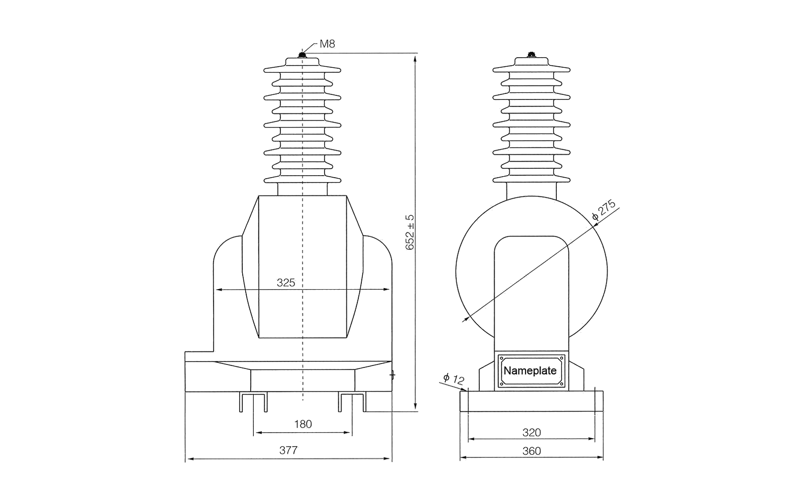
Key dimensions for layout review: M8 hardware; 652±5 mm overall height; Ø275 body diameter; 325 mm body width; 377/360 mm base references; 180/320 mm mounting references; and Ø12 mounting holes.
Electrical specification tables
JDZXW-35: Rated voltage ratios, secondary outputs and insulation data
Rated voltage ratio (V)
0.2 output (VA)
0.5 output (VA)
1 level output (VA)
3 level output (VA)
0.2/0.2 or 0.2/0.5 output (VA)
0.5/0.5 output (VA)
6P output (VA)
Maximum output (VA)
Rated insulation level (kV)
(35000/√3)/(100/√3)/(100/3)
30
90
180
500
–
–
100
600
40.5/95/200
(35000/√3)/(100/√3)/(100/√3)/(100/3)
–
–
–
–
20/20 or 20/30
45/45
100
300/300
40.5/95/200
Overall dimension drawing
Compare the mounting centres, terminals, primary interface and overall envelope with the project layout. Open the full-size drawing for closer inspection.
JDZXW-35 overall dimension drawing
Data required for quotation
Required primary and secondary voltage arrangement
Accuracy class, burden and residual or protection winding duty
Required insulation level and approved technical specification
Terminal arrangement, mounting dimensions and drawing revision
JDZXW-35 overall dimension drawing
Technical data and dimensions
Outdoor Voltage Transformer
JDZ(F)-35W2
35 kV outdoor voltage-transformer family with JDZW-35W2 single-secondary and JDZFW-35W2 dual-secondary type options.
Reference standards
GB 20840.3-2013 and IEC 60044-2
Rated insulation level
40.5/95/200 kV
Rated frequency
50 Hz or 60 Hz
Available type options
JDZW-35W2 and JDZFW-35W2
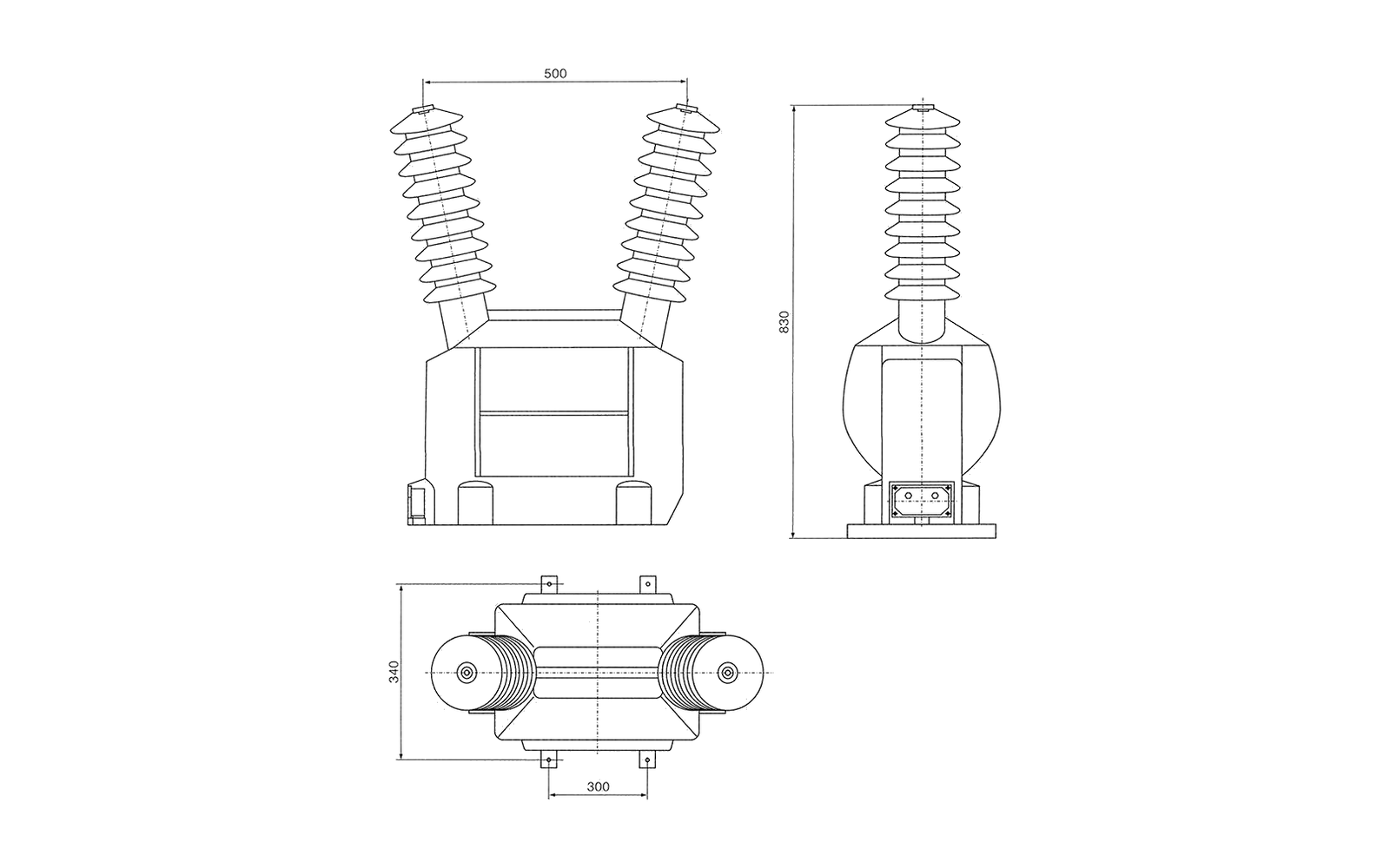
Key dimensions for layout review: 500 mm between the two top primary terminals; 830 mm overall height; 340 mm plan width; and a 300 mm mounting-centre reference.
Electrical specification tables
JDZ(F)-35W2: Type options, voltage ratios, accuracy classes and outputs
Type
Rated voltage ratio (kV)
Accuracy class
Rated secondary load (VA)
Maximum output (VA)
Rated insulation level (kV)
JDZW-35W2
35/0.1
0.2
30
1000
40.5/95/200
JDZW-35W2
35/0.1
0.5
80
1000
40.5/95/200
JDZFW-35W2
35/0.1/0.1
0.2/0.2
30/30
800
40.5/95/200
JDZFW-35W2
35/0.1/0.1
0.2/0.5
30/50
800
40.5/95/200
JDZFW-35W2
35/0.1/0.1
0.5/0.5
50/50
800
40.5/95/200
Overall dimension drawing
Compare the mounting centres, terminals, primary interface and overall envelope with the project layout. Open the full-size drawing for closer inspection.
JDZ(F)-35W2 overall dimension drawing
Data required for quotation
Exact JDZW-35W2 or JDZFW-35W2 type
Required voltage ratio and number of secondary windings
Accuracy class, rated load and maximum output
Primary-terminal spacing, mounting centres and drawing revision
JDZ(F)-35W2 overall dimension drawing
Technical data and dimensions
Outdoor Current Transformer
LZZBW-10
12 kV outdoor current transformer with standard and multi-ratio primary-current options for metering and protection duties.
Reference standards
GB 20840.2-2014 and IEC 60044-1
Rated insulation level
12/42/75 kV
Rated secondary current
5 A or 1 A
Rated frequency
50 Hz or 60 Hz
Ambient temperature
-5 °C to +40 °C
Pollution class
IV
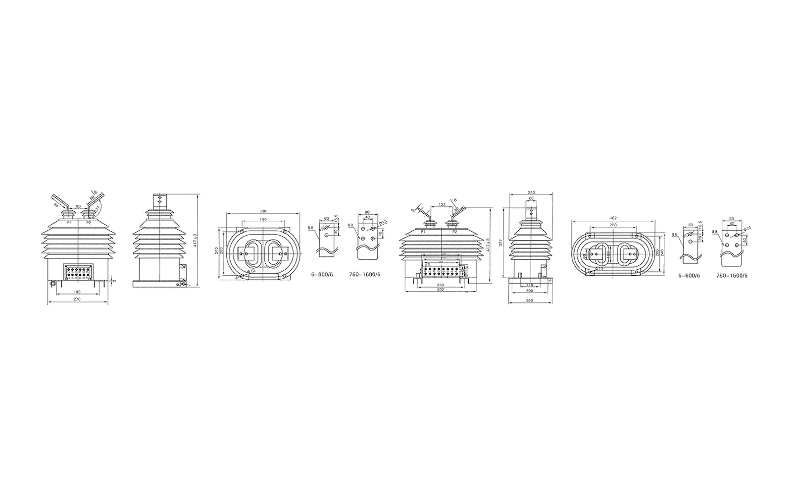
Key dimensions for layout review: Two outline variants are provided. Key values include 417±3/377 mm heights; 270/330/402/462 mm widths; 190/258 mm secondary-terminal references; 200/240 mm depths; 90/122 mm primary-terminal spacing; 110/190/200/258 mm mounting or body references; and 60/80 mm primary-bar widths with Ø13 details for the 5-600/5 and 750-1500/5 ranges.
Engineering selection notes
The primary-current ratings and accuracy or output configurations are independent option lists. Confirm the available combination for the selected ratio during technical review.
Ratings outside the listed range require engineering confirmation. Pair every requested burden with its corresponding accuracy class.
Electrical specification tables
LZZBW-10: Main primary-current and short-circuit current ranges
Rated primary current (A)
1 s thermal current (kA)
Rated dynamic current (kA)
20-40; 40
6.3
15
30-50; 50
7.5
18.75
40-75; 75
15
37.5
50-100; 100
18
45
75-150; 150
25
55
100-200; 200
50
110
150-300; 300
60
130
200-400; 400
60
130
300-600; 600
60
130
400-800; 800
60
130
500-1000; 1000
80
160
1200-1500; 1500
80
160
LZZBW-10: Main accuracy-class and rated-output options
Accuracy classes combination
Rated output (VA)
0.2/0.5
10/10
0.5S/0.5
10/10
0.5/0.5
10/10
0.2/0.5
10/10
0.2/10P10
10/15
0.5/10P10
10/15
10P10/10P10
10/15
10P15/10P15
10/10
10P20/10P20
10/10
0.2S/0.5/10P10
10/15/15
0.2S/0.5/10P20
15/15/20
LZZBW-10: Complex-variable primary-current and short-circuit current ranges
Rated primary current (A)
1 s thermal current (kA)
Rated dynamic current (kA)
10-15-20
2.7
4.5
15-20-30
4.2
6.6
20-30-40
6
9
30-40-50
9
11.5
40-50-75
11.3
16.5
50-75-100
16.8
22
75-100-150
24
33
100-150-200
33.6
45
150-200-300
45
63
200-300-400
45
80
300-400-500
45
100
500-600-800
80
130
600-800-1000
80
130
LZZBW-10: Complex-variable accuracy-class and rated-output options
Accuracy classes combination
Rated secondary output (VA)
0.2/0.2
10/10
0.2/0.5
10/10
0.5/0.5
10/10
0.2/10P10
10/15
0.5/10P10
10/15
0.2S/0.5/10P10
10/10/15
0.2S/0.5/10P20/10P20
15/15/20/20
Overall dimension drawing
Compare the mounting centres, terminals, primary interface and overall envelope with the project layout. Open the full-size drawing for closer inspection.
LZZBW-10 overall dimension drawing
Data required for quotation
Standard or complex-variable primary-current requirement
Rated secondary current, accuracy combination and burden
Thermal and dynamic current requirement
Primary bar option, secondary terminals and applicable outline group
LZZBW-10 overall dimension drawing
Technical data and dimensions
Outdoor Current Transformer
LZW-35
40.5 kV outdoor current transformer with metering and 5P20 protection options across 10 A to 2000 A primary-current groups.
Reference standards
GB 20840.2-2014 and IEC 60044-1
Rated insulation level
40.5/95/185 kV
Rated secondary current
5 A or 1 A
Rated frequency
50 Hz or 60 Hz
Ambient temperature
-25 °C to +40 °C
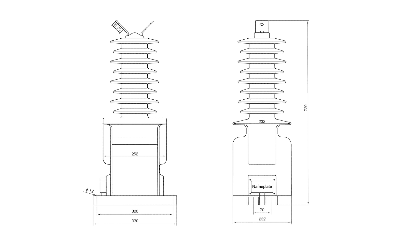
Key dimensions for layout review: 729 mm overall height; 232/252 mm body references; 330 mm overall base width; 300 mm mounting reference; 70 mm secondary-terminal spacing; Ø12 mounting holes; and a 15×30 mm primary-terminal detail.
Engineering selection notes
Accuracy and output ratings change between the 10-400 A and 500-2000 A primary-current groups. Use the row that includes the selected ratio.
Electrical specification tables
LZW-35: Accuracy combinations and secondary outputs by primary-current group
Rated primary-current group (A)
Available accuracy combinations
0.2(S) output (VA)
0.5 output (VA)
5P20 output (VA)
10-400
0.2(S)/5P20; 0.5/5P20
15
15
15
500-2000
0.2(S)/5P20; 0.5/5P20
15
30
20
LZW-35: Primary-current and short-circuit current ranges
Rated primary current (A)
1 s short-time thermal current (kA)
Rated dynamic current (kA)
10-100
200 Iin
500 Iin
150-200
37.8
94.5
300-400
54
110
500-600
68.4
136
800-1000
95.5
190
1200-2000
140
200
Overall dimension drawing
Compare the mounting centres, terminals, primary interface and overall envelope with the project layout. Open the full-size drawing for closer inspection.
LZW-35 overall dimension drawing
Data required for quotation
Rated primary and secondary current
Metering or 5P20 protection accuracy combination
Required burden, thermal current and dynamic current
Primary-terminal detail, base width, mounting centres and drawing revision
LZW-35 overall dimension drawing
Technical data and dimensions
Outdoor Current Transformer
LZZB(J)71-35W2 GY
40.5 kV outdoor current-transformer family with metering and 10P10 protection options across 30 A to 2000 A primary-current groups.
Reference standards
GB 20840.2-2014 and IEC 60044-1
Rated insulation level
40.5/95/185 kV
Rated secondary current
5 A or 1 A
Rated frequency
50 Hz or 60 Hz
Ambient temperature
-25 °C to +40 °C
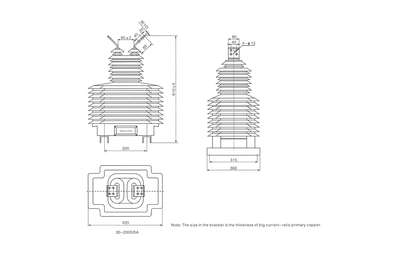
Key dimensions for layout review: 610±5 mm overall height; 420 mm plan width; 360/315 mm base references; 200 mm mounting reference; 85±2 mm primary-terminal spacing; 85/80/40/20 mm terminal references; 8(10) mm primary-copper thickness; and four Ø13 holes. The outline is marked for a 30-2000/5 A range.
Engineering selection notes
Accuracy combinations and rated-output groups are shown separately. Confirm the available combination for the selected primary-current ratio.
For the primary-copper detail, the bracketed drawing value applies to high current-ratio options.
Electrical specification tables
LZZB(J)71-35W2 GY: Available accuracy-class combinations
Accuracy classes combination
0.2/0.2
0.2/0.5
0.5/0.5
0.2/10P10
0.5/10P10
0.2S/0.5/10P10
LZZB(J)71-35W2 GY: Rated secondary outputs by primary-current group
Rated primary-current group (A)
0.2S output (VA)
0.2 output (VA)
0.5 output (VA)
10P10 output (VA)
30-500
15
30
30
50
600-2000
15
30
40
50
LZZB(J)71-35W2 GY: Primary-current and short-circuit current ranges
Rated primary current (A)
1 s short-time thermal current (kA)
Rated dynamic current (kA)
30-100
150 Ith/2
375 Ith
150
31.5/1
80
200
31.5/2
80
300-500
31.5/3
80
600-800
31.5/4
80
1000-2000
40/4
100
Overall dimension drawing
Compare the mounting centres, terminals, primary interface and overall envelope with the project layout. Open the full-size drawing for closer inspection.
LZZB(J)71-35W2 GY overall dimension drawing
Data required for quotation
Exact LZZB or LZZBJ family requirement and primary-current ratio
Rated secondary current, accuracy combination and burden
Thermal and dynamic current requirement
Primary-copper thickness, terminal holes, mounting dimensions and drawing revision
LZZB(J)71-35W2 GY overall dimension drawing
Outdoor CT and VT RFQ requirements
How to Specify an Outdoor Current or Voltage Transformer
For an accurate quotation, connect the electrical duty to the outdoor installation interface. Provide these five groups of information for new equipment, replacement transformers, metering changes or protection upgrades.
01 Transformer duty and installation
State whether the transformer is for current metering, current protection or voltage measurement, and describe the outdoor equipment, mounting position and service environment.
02 System data and CT or VT ratio
Provide system voltage and frequency, plus the CT primary and secondary current ratio or the VT primary and secondary voltage ratio.
03 Accuracy class, burden and protection duty
State each metering or protection accuracy class, rated burden or output, number of cores or windings and any required protection factor.
04 Insulation and project requirements
Confirm the required insulation level, applicable project standard, ambient range, altitude, pollution conditions and any project-specific test or document scope.
05 Terminals, mounting and commercial data
Send the nameplate or project schedule, terminal arrangement, outline drawing, mounting dimensions, primary interface, quantity, destination and required delivery date.
Select by electrical duty
Select Outdoor Instrument Transformers for Metering, Protection or Replacement
Start with the circuit function and outdoor installation, then verify ratio, accuracy class, burden, insulation level, terminals and mounting. Similar epoxy-resin housings do not make two transformers electrically or mechanically interchangeable.
01Outdoor voltage measurement
Voltage measurement and metering
Check before selection
Primary and secondary voltage ratio, system frequency and insulation level
Accuracy class, rated burden, maximum output and number of secondary windings
Primary-terminal spacing, grounding, mounting centres and outdoor clearances
Models to compare
JDZXW-35 for the listed voltage-ratio and secondary-output arrangements
JDZ(F)-35W2 family with separate JDZW-35W2 and JDZFW-35W2 type options
Confirm the exact type before approving the winding and output configuration
02Outdoor current measurement
Current metering
Check before selection
Primary and secondary current ratio and required number of measuring cores
Metering accuracy class, rated burden and short-time current requirement
Primary bar, terminal arrangement, base size and mounting centres
Models to compare
LZZBW-10 for 12 kV insulation data and standard or multi-ratio options
LZW-35 and LZZB(J)71-35W2 GY for 40.5 kV insulation data
Confirm that the selected ratio supports the required metering class and burden
03Outdoor feeder protection
Current protection
Check before selection
Protection accuracy class, rated burden, accuracy limit factor and secondary current
One-second thermal current and rated dynamic current for the selected primary range
Number of cores, polarity, primary conductors and secondary terminals
Models to compare
LZZBW-10 includes 10P10, 10P15 and 10P20 combinations
LZW-35 lists 5P20 combinations with grouped output values
LZZB(J)71-35W2 GY lists 10P10 combinations and grouped outputs
04Installed equipment
Replacement for an installed CT or VT
Check before selection
Complete nameplate, exact fitted model and every primary and secondary rating
Outdoor service conditions, project standard and approved drawing revision
Required comparison
Match the electrical configuration before comparing appearance or family notation
Use the model-specific drawing for dimensions and mounting, not a nearby model
Identify every difference for engineering approval before ordering
Confirm the exact ratio, accuracy class, burden, insulation level, terminal arrangement and approved drawing before supply.
Outdoor project applications
Outdoor Instrument Transformer Applications for New MV Equipment and Upgrades
The required data changes with the project. New equipment begins with circuit and environmental requirements, replacement begins with the installed nameplate and interface, and an upgrade begins with the revised metering or protection duty.
01New distribution equipment
New outdoor MV equipment
Define the CT or VT duty from the primary and secondary circuit design.
Confirm ratio, accuracy class, burden, insulation level, frequency and outdoor service conditions.
Set the mounting surface, primary interface, terminals, clearances and available equipment envelope.
02Installed equipment
Existing outdoor transformer replacement
Capture the complete fitted nameplate, installed ratio and secondary configuration.
Identify every electrical, environmental or mechanical difference before approving the replacement.
03Revised electrical duty
Metering or protection circuit upgrade
Define the revised metering accuracy, protection class, burden and secondary-circuit requirements.
Check thermal and dynamic current for CT duty or winding and output requirements for VT duty.
Verify that the existing support, primary conductors, terminals and outdoor clearances suit the proposed configuration.
Comparable RFQ scope
Define a complete, comparable quotation
Model and quantity
Exact model or type, ratio and required quantity.
Technical configuration
Accuracy class, burden, insulation level, cores or windings, and terminals.
Technical documents
Model data, overall drawing and agreed project documentation.
Commercial requirements
Price, delivery, destination and agreed supply scope.
Engineering and procurement checklist
Outdoor CT and VT Ordering Specifications for Engineering and Procurement
Technical approval and the purchase order should name the same model, electrical duty, outdoor service conditions, terminal arrangement and drawing revision. Use this checklist to close specification gaps before order release.
Outdoor instrument transformer order confirmation checklist
Confirm before order
Information required
Why it matters
01Exact model or type
Complete model designation, family type, quantity, equipment designation and installed position.
Prevents a family name or visually similar housing from being treated as an exact electrical configuration.
02CT or VT ratio
CT primary and secondary current ratio or VT primary and secondary voltage ratio, including every required secondary.
The ratio and number of secondaries define the metering or protection relationship.
03Accuracy, burden and duty
Accuracy class combination, rated burden or output, metering or protection function and maximum output where required.
A single family can contain different metering, protection and output arrangements.
04Insulation and outdoor service
Insulation level, rated frequency, ambient range, altitude, pollution conditions, applicable project standard and installation environment.
Keeps the electrical withstand and outdoor service requirements aligned with the project.
05Terminals and connections
Primary interface, secondary terminals, polarity, number of cores or windings and required connection arrangement.
Terminal and connection differences affect wiring, protection logic and the primary conductor interface.
06Outline and mounting
Overall dimensions, mounting centres, support surface, outdoor clearances and the governing drawing revision.
A mounting or clearance difference can invalidate an otherwise correct electrical selection.
Select by installation environment
Outdoor vs Indoor Instrument Transformers: Choose by Installation
Choose an outdoor model for exposed installations designed around the stated outdoor service conditions. For instrument transformers mounted inside medium-voltage switchgear or enclosed indoor equipment, continue to the indoor range. Start from the parent directory when the installation environment or transformer duty is still being defined.
This pageOutdoor Instrument TransformersFive outdoor current and voltage transformer models with full technical tables and overall dimension drawings.
All installation environmentsInstrument TransformersReview the instrument transformer directory and choose the installation environment first.View all Instrument Transformers ↗
Indoor installationIndoor Instrument TransformersCompare indoor current and voltage transformer models for medium-voltage switchgear.View Indoor Instrument Transformers ↗
Outdoor CT and VT engineering FAQ
Outdoor Instrument Transformer Selection FAQs
Engineering answers on CT and VT selection data, burden, standards, outdoor service conditions, replacement checks and RFQ requirements.
01What is the difference between an outdoor current transformer and voltage transformer?
An outdoor current transformer, or CT, scales primary current for metering and protection, while an outdoor voltage transformer, or VT, scales system voltage for measurement and protection. The two devices use different ratios, secondary circuits and selection criteria, so they are not interchangeable.
02What information is needed to select an outdoor current transformer?
Specify system voltage and frequency, primary and secondary current ratio, metering or protection duty, accuracy class, rated burden, number of cores, short-time thermal current and dynamic current. Also provide the primary conductor interface, terminal arrangement, polarity, mounting dimensions, altitude, ambient range and pollution conditions.
03What information is needed to select an outdoor voltage transformer?
Specify system voltage and frequency, primary and secondary voltage ratio, winding quantity and connection, accuracy class, rated burden, maximum output and insulation level. Add the primary terminal layout, grounding arrangement, mounting dimensions and outdoor service conditions.
04Why do accuracy class, burden and secondary lead length matter?
Instrument-transformer accuracy is valid only for the stated operating and burden conditions. The connected meter or relay burden plus secondary-cable losses must stay within the selected rating, so provide device consumption, conductor size and lead length when the burden is not already calculated.
05Which IEC standards apply to outdoor current and voltage transformers?
Use the editions required by the project specification. IEC 61869-1 gives general requirements for instrument transformers above 1 kV, IEC 61869-2 gives additional requirements for current transformers, and IEC 61869-3 covers inductive voltage transformers. Confirm any required GB, IEC, utility or customer standard before quotation because listed model data may reference earlier editions.
06Which outdoor service conditions must be specified?
State the minimum and maximum ambient temperature, installation altitude, pollution or creepage requirement, humidity, UV exposure, wind or seismic duty where applicable, and available electrical clearances. Outdoor capability is model-specific, and non-standard altitude or environmental conditions can change the required insulation or housing configuration.
07What must be checked when replacing an existing outdoor CT or VT?
Match the complete nameplate data first, including ratio, accuracy class, burden, cores or windings, insulation level, frequency, polarity and terminal marks. Then compare wiring, primary interface, mounting centres, overall envelope, clearances and the approved drawing revision; a photograph or family name alone is not enough.
08What should an outdoor instrument transformer RFQ include?
Include the project and equipment reference, exact CT or VT duty, all electrical ratings, outdoor service conditions, terminal and mounting requirements, quantity, destination and required delivery date. For replacements, attach clear nameplate, wiring and installation photos plus the governing outline drawing if available.