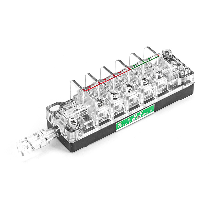
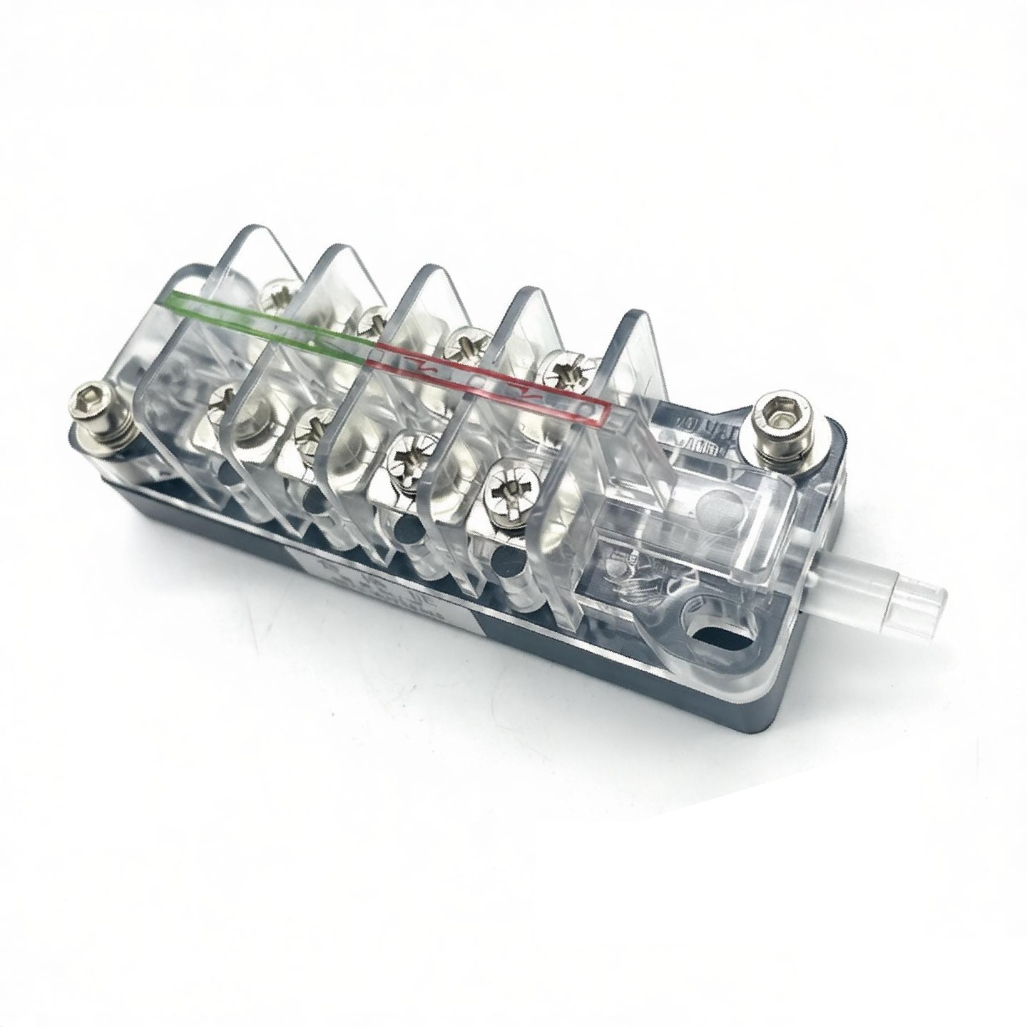
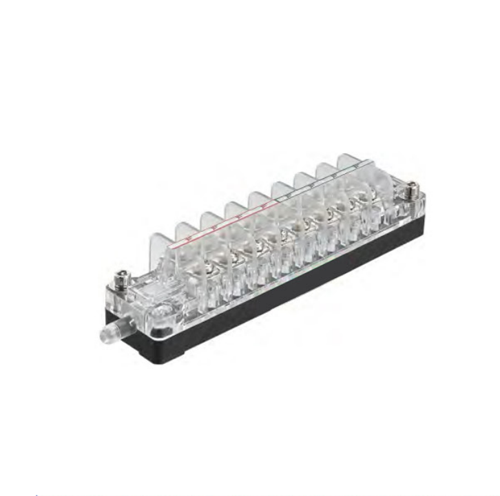
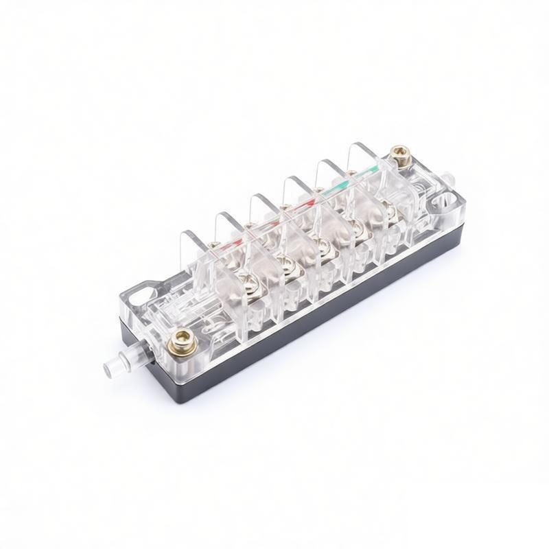
Auxiliary and Magnetic Blowout Switches for MV Circuit Breakers
Compare F10 and FK10 auxiliary switches, LXW20-11 limit switches and CSK11 magnetic blowout switches for breaker position indication, electrical interlocking, mechanism sensing and control-circuit switching.
Circuit breaker auxiliary, limit and magnetic blowout switches for MV equipment.
Browse 11 F10, FK10, LXW20 and CSK11 models. Open any card to review the model description, technical data and available drawings, then confirm the contact arrangement, actuator or shaft, mounting interface and electrical duty.
Compare the model-specific outline and installation dimensions. Open the drawing for a full-size view.
Product Description and Application
Technical Specifications
Confirm Before RFQ
Full-size drawing
How to select an auxiliary switch for an MV circuit breaker.
A reliable selection matches both the secondary-circuit function and the fitted mechanism. Send the five items below so we can compare the correct F10, FK10, LXW20 or CSK11 model before pricing.
01 Equipment and installed position
Provide the circuit-breaker, switchgear cabinet and operating-mechanism reference, installed location, replacement scope and any available nameplate or assembly drawing.
02 Contact function and wiring
Confirm the required contact arrangement, NO/NC logic, pole count, switching sequence, terminal designation and the control-circuit role.
03 Shaft, actuator and operating path
Show the shaft profile, actuator or roller form, operating angle or travel, linkage direction, fixing points and available clearance.
04 Electrical duty and environment
State the circuit voltage and current context, switching category where known, operating frequency, installation environment and documentation requirements.
05 Evidence, quantity and delivery
Send clear installed photographs, the wiring diagram or contact schedule, key dimensions, required quantity, destination and requested delivery date. A product photograph alone is not enough for a final match.
F10, FK10, LXW20 and CSK11 switch selection guide.
Choose the family from the required function: multi-pole auxiliary contacts, mechanism position sensing or magnetic-blowout switching. Then confirm the electrical and mechanical details that define the exact model.
F10Rotary auxiliary switching
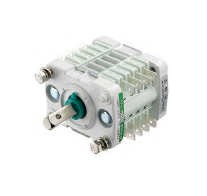
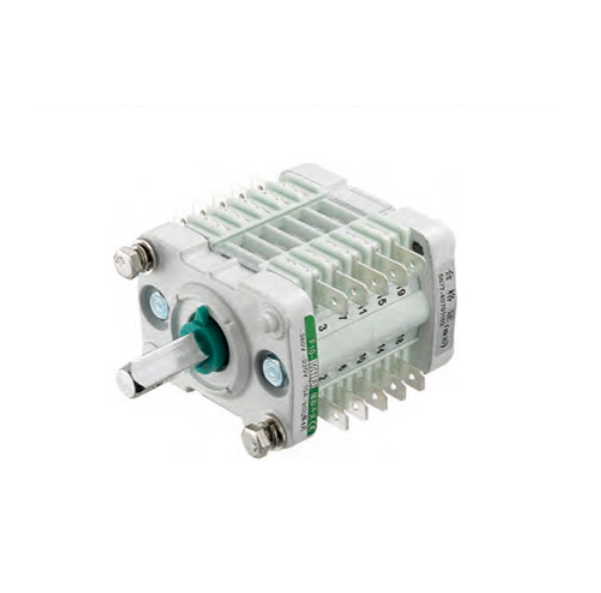
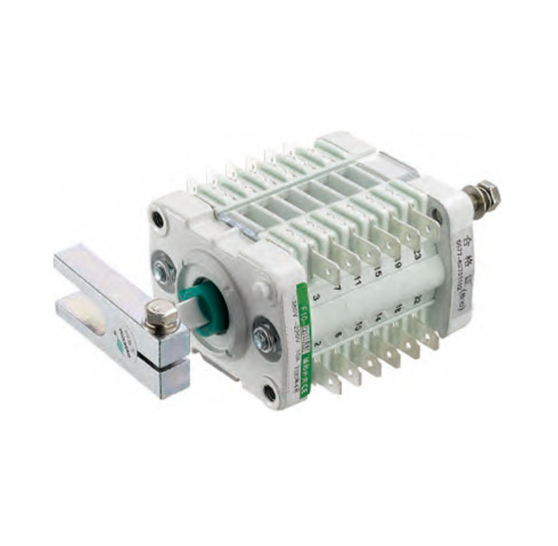
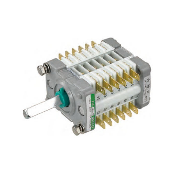
F10 rotary auxiliary switches
Choose this family when
The breaker mechanism needs multi-pole auxiliary contacts operated by a rotary shaft
The control circuit requires position indication, interlocking or sequence switching
The installed part belongs to the F10 family and its pole count can be identified
Confirm before ordering
Full F10 model and suffix, pole count, NO/NC schedule and terminal designations
Shaft profile, operating angle, linkage direction and fixing centres
AC or DC control duty, quantity and required drawing or inspection documents
FK10Mechanism auxiliary contacts
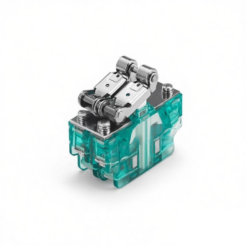
FK10 auxiliary contact switches
Choose this family when
The installed mechanism uses an FK10 auxiliary contact switch
A defined contact sequence must follow breaker or mechanism position
The existing marking, terminal layout and actuator can be documented
Confirm before ordering
Complete FK10 marking, contact diagram, terminal layout and circuit function
Actuator direction, linkage, fixing pattern and installed clearance
Electrical duty, operating sequence, quantity and delivery requirement
LXW20 / CSKPosition sensing or magnetic-blowout duty
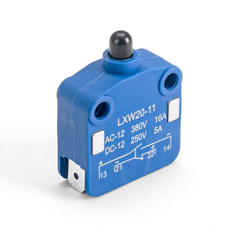
LXW20-11 limit and CSK11 magnetic blowout switches
Choose this family when
LXW20-11 is needed for roller-plunger position or end-travel sensing
CSK11 is needed for a confirmed magnetic-blowout switching duty
The request is defined by the actuator and electrical task rather than a multi-pole rotary switch
Confirm before ordering
Actuator or roller form, operating travel, overtravel and mounting dimensions
Terminal arrangement, contact form, AC or DC voltage, current and load type
Installed clearance, full model marking, quantity and required documents
For replacement projects, verify the contact logic, operating mechanism and mounting dimensions against the installed switch before ordering.
Auxiliary switch applications for new builds and replacements.
New circuit breakers, maintenance replacements and function-led projects require different input data. Choose the route that matches your project so the quotation addresses the correct electrical duty and installed interface.
New equipment
Auxiliary switches for new circuit breakers
Choose this route when
You are specifying an auxiliary or limit switch for a new operating mechanism, circuit-breaker assembly or switchgear panel.
Send with your RFQ
Required control function, contact schedule, mechanism interface, approved drawing, quantity and document requirements.
What we quote
The selected model, available technical data, price, lead time and any interface detail requiring confirmation.
Replacement
Replacement auxiliary switches for existing breakers
Choose this route when
An installed F10, FK10, LXW20 or CSK11 switch must be replaced during maintenance, refurbishment or retrofit work.
Send with your RFQ
Full model marking, contact logic, shaft or actuator, terminals, fixing points, dimensions, wiring diagram and installed photos.
What we quote
A replacement model with compatibility notes, price, lead time and any difference that must be checked on site.
Special duty
Limit and magnetic blowout switch applications
Choose this route when
The requirement is defined by roller-plunger position sensing or a magnetic-blowout switching duty rather than a known part number.
Send with your RFQ
Actuator travel or switching duty, terminals, AC/DC circuit details, load type, clearances, mounting dimensions and quantity.
What we quote
The relevant LXW20-11 or CSK11 model and the technical conditions used for selection.
What is included in an auxiliary switch quotation.
Model and quantity
Proposed model or suffix, ordered quantity and the circuit-breaker position it serves.
Technical basis
Contact arrangement, shaft or actuator, mounting data, electrical duty and available drawing references.
Compatibility notes
Dimensions, contact logic or application details that still need confirmation before ordering.
Commercial details
Price, lead time, delivery basis and the documents included with the quoted switch.
What to confirm before ordering a circuit breaker auxiliary switch.
Part number alone is not enough for a safe replacement. Confirm the contact logic, electrical duty, operating interface, mounting dimensions and supply scope before placing the order.
Product details to confirm.
Use the exact product model, contact data, electrical ratings and model-specific drawing to define the switch being ordered.
Installation details to confirm.
Use the breaker drawing, wiring schedule and installed-part measurements to verify contact sequence, linkage, travel and clearances.
RFQ itemWhat to sendWhy it matters
01
Model, equipment and quantity
Complete switch marking and suffix, quantity, circuit-breaker or cabinet reference, installed position and new-build or replacement requirement.
Prevents quotation of the wrong variant or a model intended for a different mechanism position.
02
Contact arrangement and electrical duty
Required pole count, NO/NC contact schedule, terminal designations, switching sequence, control-circuit function, AC/DC voltage, current and load type.
Confirms that the contacts perform the required indication or interlocking duty within the model rating.
03
Shaft, actuator and operating travel
Shaft profile and direction, actuator or roller form, operating angle or travel, overtravel, linkage direction and available clearance.
Confirms that the mechanism can operate the switch fully without interference or excessive travel.
04
Mounting dimensions and drawing
Fixing centres, overall dimensions, operating-axis position, terminal orientation, critical clearances, drawing number and revision where available.
Reduces the risk of a switch that is electrically correct but cannot fit the existing mounting interface.
05
Included parts and replacement scope
State whether the quotation must include the switch only or also actuator, linkage parts, brackets, fasteners or other related items.
Makes the supply boundary clear for purchasing, installation and spare-parts planning.
06
Documents, inspection and delivery
Required datasheet, dimensional drawing, inspection documents, language, file format, destination and requested delivery date.
Allows price and lead time to include the project documentation and delivery requirements from the start.
Browse more MV circuit breaker components.
Use the parent product directory when your project also requires chassis mechanisms, vacuum interrupters, embedded poles, insulation parts or other circuit-breaker components.
Current product familyAuxiliary & Magnetic Blowout SwitchesF10, FK10, LXW20 and CSK11 models for control, replacement and sensing applications.
Browse all related productsCircuit Breaker ComponentsComponent groups for new equipment, maintenance replacements and retrofit projects.View all Circuit Breaker Components ↗
MV circuit breaker auxiliary switch FAQs.
Answers to the selection, replacement, contact arrangement, limit-switch, magnetic-blowout and quotation questions engineers and buyers ask most often.
What is an auxiliary switch in an MV circuit breaker?
An auxiliary switch is mechanically linked to the circuit-breaker operating mechanism. Its contacts change state as the breaker opens or closes, allowing secondary circuits to provide position indication, electrical interlocking, relay control and alarms. Select the switch from the required circuit function and contact sequence, not from appearance alone.
How do I choose the NO/NC contact arrangement for a circuit breaker auxiliary switch?
Start with the breaker wiring diagram and identify which contacts must be open or closed in each breaker position. Then match the number of poles, NO/NC sequence, terminal designations and operating timing. For a replacement, send the contact diagram or a clear terminal photo because the same housing can contain a different contact arrangement.
How do I select a replacement F10 or FK10 auxiliary switch?
Record the full model and suffix, pole count, NO/NC contact schedule, terminal layout, shaft or actuator form, operating angle, fixing centres and installed clearances. Also provide the circuit-breaker or operating-mechanism reference. These details allow the electrical function and mechanical interface to be checked together before quotation.
Are F10, FK10, F1, F6 and ZKF6 auxiliary switches interchangeable?
Do not assume direct interchangeability. The families may differ in contact configuration, shaft-to-mounting dimensions, operating angle, linkage and terminal arrangement. Send the installed marking, contact diagram, mechanism photos and outline drawing so the proposed replacement can be checked against both the circuit function and the fitted mechanism.
When should I use an LXW20-11 limit switch instead of an F10 or FK10 auxiliary switch?
Use LXW20-11 when the mechanism needs roller-plunger position or end-travel sensing. Use an F10 or FK10 family switch when the breaker mechanism must operate several auxiliary contacts in a defined sequence. For LXW20-11, confirm the actuator path, operating travel and overtravel, terminal layout, fixing holes and available clearance.
What does a magnetic blowout switch do, and when should I select CSK11?
A magnetic blowout design uses a magnetic field to move the switching arc away from the contact gap, which is useful for demanding DC control-circuit switching. Select CSK11 only after confirming the model-specific voltage and current duty, load type, contact form, actuator, terminals and mounting dimensions against the application.
Which electrical ratings must be confirmed before ordering?
Confirm the exact model rating, AC or DC supply, circuit voltage, continuous or switched current, utilization category or load type, switching frequency and expected mechanical or electrical life. Do not apply one model’s rating to another F-series, LXW or CSK switch. Use the model data sheet together with the actual control-circuit duty.
What information should I send for an auxiliary switch quotation?
Send the circuit-breaker and operating-mechanism reference, complete switch marking, contact schedule, wiring diagram, shaft or actuator details, mounting dimensions, installed photos, quantity, destination and required delivery date. For LXW20 add the roller-plunger travel; for CSK11 add the circuit voltage, current and load type.